or “Ed’s views on engine building and tuning”
(Engine Assembly and Tune-up at end of this section)
My experience comes via “the road of hard knocks”. In the early days we didn’t have any accurate tuning aids or decent race gas. Burn things up and “Whoops, must be a little lean”. I have been racing a supercharged early hemi since 1972 so have experienced many problems. If I mention something in this write-up it’s because it works for me. You will have to analyze the data and do what YOU think will work best for you. Check back occasionally for “Revisions” shown at the end of this write-up. I try to do a complete update at the end of each calendar year. Your feedback will help keep things accurate.
There are very few (if any) running an early hemi in a NHRA class. Therefore, obtaining maximum horsepower is not an issue for racers like you and I that fall in the “other” category. If you want to run in a 7.60 nostalgia class like NE1, you don’t need 1500 hp in a light car.
For nostalgia eliminator, I have a very conservative setup: 354 (365″) on alcohol, 10:1 compression, 8% under driven standard helix 6.71, 22 degrees of lead and my old Engle F31 hardface cam with .600 lift. The car weight is 2200 lbs. with Powerglide and 4.56 gears. This combo ran an easy 7.55 @ 175 mph at the Bakersfield “March Meet”. Elevation at the track is about 600′.
First we’ll talk about the individual components and then follow-up with engine assembly, tune-up and revisions. If I have omitted anything, you find an error or just disagree, please let me know. I am posting this information as an aid for those new to a supercharged early hemi. If I can help minimize broken or burned up engine parts, we’ll call this write-up a success. If you like what you see, let me know through texting my phone or email.
Individual Components
Block
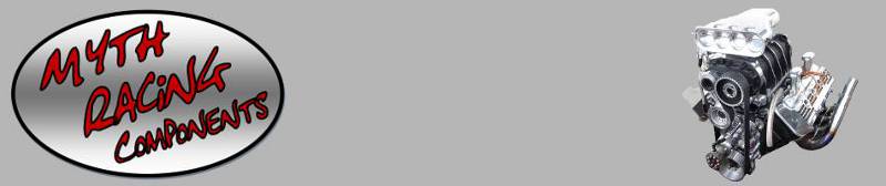
Block selection should be made with the intended use in mind. If you need lots of horsepower a 392 would be the choice over a 331. If you’re putting together a street machine, I would use a 331 or 354. They look the same as a 392 at half the cost. If utilizing a supercharger you’ll have more power than you can handle with the smaller engines. Availability in your area also plays a role. If you have access to a certain size complete engine – use it. You can also use a Spitfire poly block. See “Oil Pump” section for modifications required when using a hemi oil pump. I’ve included a picture of the rear of the Spitfire poly block for ID purposes – this is a 58W 354.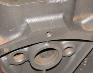
I have read a lot of comments on the so-called hi-nickel “W” blocks. I have never seen any difference in longevity when running a “W” block and would not pay a premium to obtain one. One of the “Petty boys” told me all the hemi blocks were hi-nickel so what can I say.
This paragraph was added recently to aid in block selection. I have a 354 block that has main caps from another engine. Obviously this would need an align bore if not already done. Any purchased block should be checked by a machine shop for a good main bore. Prior to purchasing, if possible, check to see if the factory machine marks from block to main cap line up. These marks are very obvious on the front and rear of the block. They are not so obvious on the center (3) mains and you will need to take a closer look. If you are going to use a block from a running engine, you are pretty insured the main bore is OK. Just something else to check. Here’s a close-up of my block with mismatched cap. All machined marks should line up. 
For most street and some drag racing applications a 2-bolt block is fine. My first purchased engine was a supercharged 331 with 2-bolt mains. This ran OK in a light weight dragster but in a 2900 lb. coupe it destroyed pistons and “rattled” the mains on a regular basis. I ran this block for a year and never cracked a cap or the main webbing. An advantage of the 2-bolt setup is not having to worry about water leaking into the pan as sometimes happens with the 3/8” splayed bolts on a 4-bolt setup. I have only seen a couple of blocks where the 3/8” bolts didn’t break through the thin part of the main webbing. Extra care must be taken to seal these areas. Another 2-bolt advantage is the elimination of the costly align boring process. If you are marginal on the requirements to go to a 4-bolt setup you can take a much less expensive route. For my second 2-bolt block I milled the tops of the center three caps and made ground steel straps as a form of reinforcement. If a cap were to crack, the steel support would likely keep things together. I never cracked a cap with this setup.
All my engines now have the 4-bolt caps as extra insurance. I do not use a steel front cap and have never had any problem although my fuels have been limited to gasoline, alcohol and 20% nitro. If you’re running a lot of boost, or utilize heavier percentages of nitro as a fuel, you can make a steel front cap as an extra precaution. I would not use a 4-bolt front cap as the outer bolts are not in solid material and could weaken the block. For the center three caps, steel or aluminum works OK. Although most caps are steel (or cast), the aluminum caps seem to absorb the shock well as indicated by a reduction in movement between the cap and block.
Billet rear main cap – I do not recommend one. I call this a “one time use item”. Here’s why: When first installed there is no problem as the cap has material for align boring. If you damage your block and decide to use the cap on another engine problems can arise as the mounting surface of the cap will need to be machined down to accommodate align boring. How much material will need to be removed to provide for a satisfactory cleanup? Probably unknown until the cap is mounted on the block. Just a .001 sideways displacement will require facing about .050 off the cap to ensure a full cleanup at the parting line when align boring. When you do this, what happens to the tang for the oil seal? It drops .050 toward the centerline of the crank making the seal ineffective unless all surfaces related to the seal are machined. Problem solved – NO! What about the pan seal? It has also dropped .050. Now you’ve got a leaker! But, my personal favorite is: I’ve beat these things to death and never broken a rear cap. So why spend the extra bucks when it’s not necessary? With ARP studs I doubt if you’ll ever have a problem.
Note: If you are considering a complete billet set of main caps (5) give me a call or drop me a line. I have found some dimensional problems with some aftermarket rear main caps. I will send you a sketch showing you the areas of concern.
Installation of new 4-bolt caps:
- Clean registration area in block.
- Depth mike steps in block for #2, 3, 4 mains (both sides) – record with marker. Should be around .125.
- Mill #1 and 5 caps (if originally on block) down .003- .005. This will maintain a good seal on both rear main seal and pan seals. Check with your machinist – he may want a different amount. Another consideration is the affect on your timing set. If you take too much off the block, it will necessitate purchasing a special timing set with oversize cam gear or undersize chain. If using a gear drive, you will need an undersize crank gear if there is no backlash in the gears. The minimum backlash should be about .003-.005 to provide for oiling, yet not excessive to affect timing.
- Mill steps in 4-bolt caps to match recorded dimensions from item 2, if required. On #3 cap, be sure to indicate forward or rear cap face to within .001 vertically before machining to insure equal contact on both top and bottom bearing halves.
- Install #3 4-bolt cap. Align thrust surface (rear face) with surface on block.
- Flat bottom drill through splayed holes to surface of block – I recommend obtaining a flat bottom drill and spotfacing the surface of the block before drilling the 5/16 hole. If you do not spotface first, the drill will walk to the outside when it hits the block and make the bolts tight in the caps. It also nibbles away at the supplied 5/16″ ID drill bushing so each hole gets a little worse. Even with the spotface you may have to open the holes in the caps a few thousandths as they are close to the bolt size. A flat bottom drill to fit the splayed holes in your cap can usually be found on ebay. Try to find one with a small corner radius or chamfer to minimize the chance of chipping the edge.
- Install 5/16 I.D. bushing – Drill 5/16” holes into water jackets. You will probably need a 6” extension drill or 12” aircraft drill from the hardware store or online. Carbide or cobalt is best as cast iron is abrasive.
- Remove bushing – Tap 3/8”-16 through with extension tap.
- Repeat for #2 and 4 caps.
The bores on new caps are undersize – no further preparation required.
Installation of used 4-bolt caps – NOTE: I have removed this section as too many variables affect the installation and I find it counter productive for you to install used caps or pay a machine shop to do it. New caps are the way to go.
Cracks – Check block carefully for cracks. If there are any cracks running from the head bolt holes to the water jacket holes or cylinder wall to the water jacket holes and you are running alcohol, don’t use it. Too much cylinder pressure is produced. The block in the picture cracked in this area on #1 cylinder when a sleeve was pressed in. It continued cracking all the way across to #7 and also down the cylinder walls.
There was no detonation going on – just normal operating cylinder pressure. Not visible is a hole in the left cylinder wall providing a route for the flame to pass by the rings and piston skirt – looks like a piston out of a fueler! I have run blocks with small cracks in the areas described where the horsepower output is below 750 with satisfactory results. These were supercharged gas engines. Other areas to check are of course the main webs as well as externally near the deck and about an inch above the pan rail. If you have a welder familiar with cast iron you can have the external cracks repaired. If running water, silicone over the weld to eliminate the possibility of a leak. Once the visual is done, have the block magnafluxed to uncover other gremlins. If available to you, a sonic test is a little extra insurance against core shift.
Sleeves – Do not use standard cast iron sleeves on a high horsepower engine. Go to a sleeve manufacturer like Darton and order ductile iron sleeves with a .187 wall (.125 min if supported). I do not recommend the common step sleeve. There are advantages to a step sleeve, BUT, they also eat into the deck and weaken it. Hemi blocks have pretty thin decks (about 1/2 the thickness of a small block Chevy) and we don’t want those nasty cracks starting. Take another look at the pictures. I recommend a step at the bottom of the bore for sleeve location.
Block cleaning – If you are going to run alcohol with a filled block or gasoline with a filled or partially filled block, the inside needs to be clean so the filler will be tight against the cylinder walls. You don’t want .020 of rust or sludge between the block and filler. It’s best to use a process that removes the crud like a Wheelabrate process, ultrasonic, baking, etc. Make sure you remove the oil gallery plug located in front of the oil pump drive gear. The larger plug in the rear of the block is just a cover. If you chase the threads on this plug (or install a different one), make sure you check for interference with the distributor drive gear. If touching, grind some off the end of the plug.
Interior Paint – Just like the old days, I use Rust-oleum Chestnut Brown. The engine stays cleaner and looks nice with an internal paint job. The valley can be partially sprayed and then finished with an artists brush as long as you don’t shoot into the lifter holes. The crankcase side must be completely painted by hand. Plan on spending about 3-hours. Note: If you are running alcohol and leave alcohol contaminated oil in the pan for any length of time it will start to degrade the paint.
Block filling – In my supercharged gas engine I ran water in the block without filler and it worked fine – no split walls. With an alcohol engine, I would definitely run a filler for additional support and rigidity. When filling the block, level front to back. Install cylinder heads using plastic sheet ( heavy drop cloth material) as a gasket. Turn engine upside down and fill through the freeze plug holes. Let stand for a week before removing heads. This process fills to the very top of the block. If you try to fill from the deck side it’s too messy to fill all the way to the top. In addition, the filler shrinks after drying. Copper head gaskets (without water holes) will then sink into the holes from heat making it difficult to reuse them on a different block. I like Moroso filler because it comes in four bottles for mixing.
Head studs – OK, but not a requirement for a street engine since you’re not going to be tearing it apart on a regular basis. Studs will preserve the tapped holes in the block if it’s coming apart often. If you’re going to “crank it up” (alcohol over 11:1, lots of boost or nitro) you will want to consider 9/16 studs for added holding force. Hey! I make a kit for drilling and tapping the existing holes to 9/16″. Check out my “Products” section. Do not hand drill these holes! You want these holes perfectly perpendicular and centered so don’t try eyeballing for location and perpendicularly. Just a few thousandths out of perpendicularly at the block could result in 1/4″ at the top of the stud. Note: Considering the thin deck, I don’t drill through the cast boss for the head bolts when installing 9/16″ studs. This is just my preference to preserve strength but have no data as to whether it is effective or not.
Boring, decking, etc – SOP machine shop stuff. All my blocks are 4.000 bore and have never had a problem with cylinder walls on either alcohol or a small percentage of nitro.
Block honing – The pros always use a honing plate. Then again they’re looking for that extra 5 hp with standard rings. On my hemi, the difference in leak down is about 8% more without a honing plate than it is if one is used. Here’s my advice: If available for your bore size, I would use a .017 Dykes chrome stainless or ductile Fire Power top ring from BWE Piston Rings (Bruce Walker). If you do not have access to a honing plate, go without it. Performance wise, there is no difference when using a Dykes ring. In a full throttle situation they will seal with 50% leak-down. IF the Dykes is not available, you will probably need a hardened ductile ring. If this is the case, you will need to use a honing plate as these rings are not as flexible and not constructed to exert the pressure on the wall like a Dykes. The standard hardened ductile iron rings do exert more static pressure but not as much as the Dykes under power. For a street setup both these types of rings are too severe on the cylinder walls and you should go with something like a Total Seal. Not many machine shops have a honing plate for an early hemi. If you’re going to do a lot of racing I would invest in your own plate. BHJ makes a nice one but they’re expensive. Note: The hone for the Dykes is 320. If purchasing a Flex-hone for up to 4″, it is a GBD40032 (white paint on nose = 320 grit). I use a 25-35 degree cross hatch but anything close is fine. Check with manufacturer for other rings. Note: BWE Piston Rings (Bruce Walker) can usually custom make dykes rings in the more popular sizes. In some cases they can use a standard ring and cut the Dykes step. Bruce can be contacted at 208-832-8750. Tell Bruce that Ed Middlebrook referred you and he will give you the best deal possible. I’ve been buying rings from Bruce since the ’70’s.
O-ring / receiver grooves – Most builders o-ring the heads and put receiver grooves in the block. This method provides extra protection for keeping the gasket in place. The receiver grooves only need to be about .010 deep. Deeper just weakens the deck surface. If you’re going to o-ring multiple blocks, invest in an Isky “Groove-O-Matic”. I think I got mine through Competition Products. You can also use the Groove-O-Matic cutting head to cut o-ring grooves in the head. You’ll need to make an adapter to fit one of the cheap (Chinese) single point fly cutters that use a brazed or carbide lathe tool. I’ve seen them on ebay for about $25. I made the adapter shown in the fly cutter.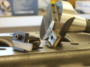
I machined it flat and then heated and bent it to make the o-ring blade perpendicular to the Bridgeport table. The cutter assembly to the left is from the Isky “Groove-O-Matic” kit. You will need to rotate the grooving cutter super slow so as not to oversize the groove. If you already have o-rings in the block, spray the head white around the combustion chambers and mount the head to block. Add a couple bolts or studs and tighten to about 25 lbs. Remove head and use the impression made by the o-ring to center on mill. This method also works to locate the receiver/o-ring grooves on the block surface.
As noted below, I destroyed my good set of iron heads and had to go with an old set of Webster aluminum heads. The existing receiver groove diameter in the block was not in the same location as the o-ring diameter in the head. The o-ring groove diameter in the head was about .100 larger than the diameter in the block. I decided to deepen the receiver groove in the block to accommodate an o-ring. I used two o-rings which has worked well. This is not advisable if the two grooves are close to aligning with one another as it would tend to cut the gasket.
Intermediate Shaft Bushing – Check the bushing in the block for wear by using the intermediate shaft as a gauge. These bushings sometimes crack at the seat (not visible) or are damaged during the block cleaning process. To be safe I always install a new one. After breaking a bushing at the track, I now fabricate a removal and installation tool. Check the “Products” drop-down on my website for this handy tool.
Factory oil holes – I have seen the oil drain-back holes as well as those in the mains drilled out. Some of the “old timers” say this helps but I leave mine “stock”. If you’re running a small cubic inch class engine at 10,000+ rpm, oiling may need further consideration. For what we’re doing just leave them alone. Stock holes worked fine for my 9000+ gas motor. I have received a few calls noting they’ve been told the early hemi is not a RPM motor. From my experience the only RPM limitation is the long exhaust rocker arm coupled with extreme cam lift and the spring pressure required to avoid valve float. I’ve never had a “bottom end” oiling problem. If you own a 392 there are some rpm limitations due to the larger journals, piston speed, etc. It’s kind of like the BBC vs SBC comparison.
Oil diverter (bypass) assembly – This is the check ball assembly under the rear main cap. This is usually removed in favor of an aluminum diverter without a check ball. The aluminum diverter just drops in the existing hole and directs ALL oil to an external filter. One negative is that they restrict oil flow by about 20% – more restrictive if the diverter turns thereby blocking part of the hole going to the filter. The holes in the pump and cap are .500. The hole in the block where the diverter drops in is about .572. Take away the wall thickness on the drop-in aluminum diverter and you restrict the flow down to about .406 where oil exits to the filter. There are three options: 1) Tap the hole and use a plug to block off oil flow between the two holes going to the filter pad. 2) Use the standard aluminum diverter. 3) Buy one of my aluminum high-flow diverters that will flow close to .500 diameter – Additional information and pictures in the “Products” section. This diverter will flow 20 – 50% more than ANY bypass on the market.
If you are running a street setup and want to use the stock oil filter adapter/canister, just clean and re-install the stock bypass assembly.
The stock bypass is in two pieces and sometimes hard to get out due to rust, etc. If unable to remove using a piece of rod through the oil pressure hole or you intend to reuse the stock bypass, take a hammer and lightly tap an EZ OUT into the hole in the bypass assembly. Twist counterclockwise and lift to remove. Remove ball bearing. The bottom section has a 5/16 hole that can be tapped to 3/8-16. Starting the tap may be a little difficult since the bottom piece of the diverter has two short tangs pointing upward – eventually it will go. Use a 3/8-16 bolt and washer as a puller. Warning: Removal by any method may render the assembly unusable.
Crank
Hemi cranks are tough. I’ve never had a problem with a prepped stocker and had well over a hundred tough runs on the one in my gas engine. If running on alcohol, I would recommend sending it out every season for a wet Magnaflux. A dry mag just doesn’t cut it. I’m currently somewhere around 1000 hp with 65 runs on the crank and #1 rod journal cracked. This crank also had a few runs on 20% nitro so it may have been weakened somewhat. A front crank support would extend the crankshaft life if supercharged. For 2025 I am working on a reasonably priced support – check back.
Used cranks – If you’re going to run a used crank “as is”, place it between #1 and #5 mains bearings (2, 3 and 4 removed) and check them for run-out. This should be less than .001 (0 – .0005 preferred). If more, have it straightened. It’s also mandatory to have it wet magnafluxed. A note on main bearing run-out: Any reworking of the rod journals will likely tweak the mains necessitating a main re-grind. Check all mains for runout. Be sure to check the flywheel flange for runout. This becomes critical if running a clutch and heavy flywheel.
Crank grinding – I am using Henry Velasco at Velasco Crankshaft Services (562-862-3110) or Joe Castillo at Castillo’s Crankshaft Specialists (714-523-0321). For racing I have the rods and mains turned .0015-.002 undersize (.0005-.001 for the street). This yields somewhere around .003-.0035 clearance. I also have the crank ion gas nitrided. The throws should be 2″ wide. Check with your rod manufacturer for the rod width. They should be in the neighborhood of .980 to provide about .040 between rods – there should be at least .030. If the clearance exceeds .040 after installation, don’t worry as I have seen clearances up to .070. If you want a little extra clearance on the thrust main, this is the time to do it. Shoot for about .012-.014. A popular practice is to turn the throws down to big block Chevy size (2.200) to provide for a better selection of bearings.
Note:
Grooving and/or cross drilling – I have purchased a couple of cranks with this type of prep and they worked OK on low rpm engines so I can’t give grooving and/or cross drilling a thumbs up or down although there’s plenty of controversy on the subject. For high rpm engines I would NOT use a cross drilled crankshaft as oil starvation can occur. There’s a pretty good explanation on the Reher Morrison web site. See #51 under Tech Talk – RM is definitely against cross drilling. Oil hole diameters should be ¼” for high rpm applications (354 crank). Cranks with 3/16” holes (331) are OK for rpm below 7000. If you have a 331 crank with 3/16 holes and will be running a higher rpm, have the holes opened up before nitriding or select another crank. Below is a PDF from Vandervell / Mahle on main bearing groove length. Just something to add confusion but very interesting. http://www.vandervell.co.uk/images/slideshow/homepage/1285170047TheInfluenceonMainBearingGroovesonBearingPerforman.pdf
Stroking – If you decide to increase the stroke, it is important to consider the modifications required to the block and/or pan. Excessively long strokes will eat away at the water jackets and pan rail often necessitating an elaborate and expensive pan along with the possibility of an internal water leak.
Install a piston/rod and swing the crank to see where the clearance problems occur – record the readings. Some minor clearancing of the block may be necessary with aluminum rods and a stock stroke crankshaft.
When adding a longer stroke crankshaft, you will want to check three areas: 1) Rod beam as it passes the bottom of the cylinder 2) Big end where it passes the bottom of the cylinder and the pan rail 3) Big end rod bolt where it passes the bottom of the cylinder and the pan rail.
When finished with your measurements and trying to decide on a stroke, keep in mind you can go twice the clearance in stroke increase. Let’s say with a stock stroke crank everything clears the pan rail and/or pan by .320. You could increase the stroke up to 1/2″ (1/4+1/4) and still have .070 clearance (.320-.250=.070). When you’re looking at as little as .070 clearance you will need an accurate representation of the rod you’ll be using.
Note: The inside of a stock pan measures about .550 from the centerline of the pan bolt. A rod will usually contact the pan before it contacts the pan rail where it steps down. The pan rail step is about .500 inboard from the centerline of the pan bolts.
If you decide to run small block Chevy rod journals you can get a free increase in stroke when the throws are ground. Pickup 20+ cubes without welding due to the smaller Chevy journal size. The downside would be the inability to increase the fillet radius thereby eliminating the stock rolled undercut. The stock fillet can also be welded up to provide for the larger finished fillet but I shy away from any unnecessary welding – just me. Check with your grinder. Increasing the fillet radius on the rod journals takes away from the maximum increase in stroke. BUT, a larger fillet also adds strength. Try to maintain a minimum of a .090 fillet (.120 preferred) for racing applications. A .120 fillet will add significantly to the longevity of the crank. If the crank is to be used for the street, OK to increase the stroke.
If you already have a 331, 354 or 392 stroker rotating assembly, use what you have – don’t spend the extra bucks.
Main bearings –The only prep to consider here is on the thrust surface (rear) of the center bearing insert. Using a triangular file, I add three grooves by about 1/16” wide to both upper and lower rear faces. This is particularly important if you are running a clutch. When you depress the clutch and hit the throttle, the crank presses against the rear thrust surface and cuts off oil flow. Without the grooves the thrust surface is usually shot after a few runs. OK, If you leave at a low rpm it may be fine. I’m talking about a hard leave.
Although I have not had any further problems with the stock thrust bearing after the modification described above, you can also opt for a roller thrust bearing between the #1 main cap/block and the front counterweight. This option requires creating a machined undercut in the front counterweight to account for the thickness and diameter of the roller thrust bearing + (2) accompanying hardened washers that serve as the races. If you are familiar with the popular thrust bearing used to keep a Chevrolet cam from moving forward or aft, they look the same only larger in diameter.
The first thing in calculating the depth of the undercut is to make sure the rear surface of #1 cap and the block are perfectly aligned. If OK, install a new stock center thrust bearing, then install the crankshaft and push it forward against the thrust surface of the bearing. Measure the gap between the #1 main and the front counterweight. Assuming the gap measures .150 and the total thickness of the thrust bearing with side washers is .250, the undercut in the counterweight would be .100. However, you would want to subtract .002 -.003 from the calculated depth thereby pushing the crank rearward so the thrust surface of the crankshaft never touches the rear of the stock thrust bearing. If calculated correctly, you shouldn’t see any wear on the rear face of the stock thrust bearing. Now if you screw up and it does touch by a few thousandths, I wouldn’t panic as the roller bearing will prevent a complete wipe-out of the stock bearing. Since the undercut depth must be close, the machining is best done locally where the depth can be checked and re-machined if necessary. Also as a reminder, this step should be done prior to nitriding.
Once a roller thrust bearing is installed, it is now possible to use a thrust bearing with a bad thrust surface. I have a few of those.
Bearing selection – Unless you can find an old set of Clevite 77 bearings (MS1417) you’ll have to go with the King bearings which work just fine.
Note: For rod bearings see “Rod Bearings” below.
Flywheel Flange – A stocker comes with holes for “through bolts”. If you have a “virgin” you will want to tap these out to 1/2-20. I make a quality tapping block that will ensure the tapped holes are on-center and perpendicular – check out the “Products” section.
Pistons – Recommendations for compression:
Supercharged gas – street: 8:1
Supercharged gas – strip: 9-10:1
Supercharged alcohol: 10-12:1 (Over 10:1 the use of 9/16” head bolts is recommended).
Compression – The procedure below assumes an obtainable compression ratio without custom machining the entire piston dome. It does not cover every detail of the machining as this would take pages. Checking valve to piston clearance first ensures an accurate calculation.
The compression ratio is basically the entire volume of the cylinder (piston installed) at bottom dead center divided by the volume at top dead center.
Let’s take a paragraph to discuss compression on the 331 or 354 engines and why I never worry about it. On a 331, you’ll be lucky to get 9:1. You might be able to get a little more if you work at it but you’ won’t see any appreciable gain in HP so why put the effort into it. My 354 (365 ci) has a moderate dome and is about 10:1. I could add a little more dome for maybe 10 1/2 :1. Since I race this engine, maybe 186 mph instead of 185. It’s not worth my time. If you do race, the biggest increase in performance will come from adding alcohol in addition to increased boost if using a supercharger.
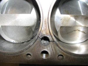
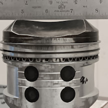
This gives you some perspective: I was in the middle of an engine build and wanted to run an upcoming meet. The only 4″ bore assembly I had was for use with gasoline. The piston domes were caved in from heat so maybe 7:1. Together it went. 7.70 et @ 175 mph on alcohol. My best with the 10 1/2 : 1 engine was 7.35. So, even with super low compression, it’s still going to run. See pic.
Supercharged gas can be a little tricky as it burns hotter than alcohol. The top of the gas piston shown below is caved in about .100. The thickness at the dome and valve reliefs is .250/.270. A little extra material here is recommended as a starting point until you get the tune-up close.
So, let’s go on to checking valve to piston clearance followed by calculating compression – for those that care.
For a 331 or 354 you will need a piston of the correct bore. An option is to check the “Hemi Swap Meet” on the Hot Heads web site or Racing Junk for used pistons. If you can find some in your size it will save you money and assist in ordering new pistons.
Valve to piston clearance
- Clay up the valve reliefs on the junker piston and assemble engine with TDC set, camshaft you’re going to use installed and degreed in, head gasket and valve train installed with valve lash set. I cut the clay into strips so it is less likely to stick to the valve.
- Rotate assembly two rotations to determine valve to piston clearance and disassemble. I run about .150 intake and .190 exhaust although these numbers could be as low as .100/.130 if you’re looking to increase compression on the smaller engines. There is an added advantage to running the closer valve to piston clearance – more thickness from the valve relief to top ring groove. Also, I like a little more clearance so I can safely advance or retard the cam if necessary. If you don’t have enough clearance, mill the reliefs down and to the correct diameter for your valves. Piston manufacturers usually come off the valve reliefs with a 45 degree cut to provide a little more meat at the top ring land to dissipate excessive heat – try your best to simulate this cut as seen in picture below. Note: Top ring placement should be as close to the top of the piston as possible given all of the variables noted. For supercharged gas a lot of heat is generated. The distance from the deepest part of the valve relief to the top ring groove should be at least .125. You can adjust all the clearances/thicknesses once you run your combo and gain confidence in your tuning ability.
- Assuming your junker piston doesn’t have a huge popup and you want to increase compression, clean the dome thoroughly (shinny aluminum), drill 8-10 1/4″ holes in the dome area, scuff up the remainder with coarse sandpaper and put a masking tape “dam” around the piston. Fill with Bondo except where the valve reliefs are located.
- Turn outside diameter on a lathe as well as a 45 degree angle (see side shot) to simulate the curvature of the dome of the head.
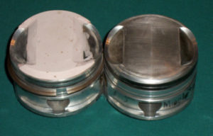
5. Keep the 45 degree angle as close to the combustion chamber as possible – say .030 (where the Bondo meets the aluminum in the picture). If you want more compression, or your engine is of a smaller displacement, add a little more to the top later. If compression is too much, take a little off. When you get it looking something like mine (see photos) it’s time to reinstall in the block and go for a cc check. For accurate results you’ll need the long 100 ml lab burette. Note: 1 ml = 1 cc.
6. Grind one of your new top rings to obtain a 0 -.002 end gap. Use a small amount of Vaseline on all surfaces of the ring and install on piston. After installing piston/rod in engine move about 1″ down the bore. Put a thin film of Vaseline on the bore and move piston to TDC.
7. Use carpenter’s level to level head surface of block in two directions.
8. Add head gasket and head – no valve train required. Do not rotate assembly – keep at TDC.
9. Fill burette with water – I usually use ATF but you don’t want to get the Bondo oily in case you need to add some additional material for a re-check.
10. Fill the combustion chamber through spark plug hole until it is full. When full, record the cc’s used. Check for water passing by the rings and dripping out the bottom. If water is leaking fix the problem and retry. If you can’t stop the leak, try ATF.
11. To calculate compression, multiply bore squared x stroke x 12.87 (= cc’s) and add to cc’s found in 10. then divide by cc’s in 10.
12. If interested in the combustion chamber cc’s, remove head and using a Plexiglas cover with hole, cc the combustion chamber in the head for future reference. Chrysler heads are around 110 cc’s. Use a little Vaseline to seal the Plexiglas plate. Add clamps if necessary.
13. Re-Bondo, rework, re-cc until you get the desired compression. Note: The piston shown in the picture above has intake and exhaust reliefs of the same diameter so piston placement is not important. If additional compression is needed, the exhaust relief can be reduced in size. You might gain 1/4 – 1/2 point in compression.
14. Send piston to your favorite piston manufacturer. Order 10 pistons and 8 quality pins with aluminum buttons. Price about $1100.
Piston to wall clearance on a supercharged engine should be at least .010-.012. I’ve used pistons up to .020 – same performance. You can also opt for a coated skirt to minimize galling – of particular importance on a supercharged gas engine. Be sure to take a little extra off the skirt to compensate for the coating if required. Check with manufacturer. If sending the piston manufacturer a sample piston, make this check. Place a ¼” diameter punch, rod or drill (upside down) in a vise and touch off the top with a 1” travel indicator. Zero indicator. Slide piston onto the rod or drill and read the thickness through the dome and valve relief areas. You want about .250 for a supercharged gas applications – .200 OK for alcohol for your first build. With a permanent marker, mark the thickness on the top of the piston at various locations. Once completed you will get a pretty good idea as to where the thin and/or thick areas are. The piston manufacturer can then position the finished piston within the piston “blank” to provide the proper thickness. They can also lighten the pistons in the thick areas and add skirt coatings if desired. Lightening for an alcohol application is definitely worth while as it reduces rod bolt stretch.
15. Reinstall new piston in block and re-cc. Recalculate to find your alcohol pistons are 10:1 instead of the desired 10 1/2:1. Don’t worry it will still run fine – add some to the dome on your next order. If compression is too high just face some off the top and re-cc. They never come out exact on the first go around. You can also deliberately order the domes a little high, cc the assembly and then machine some off to obtain the desired compression. Note: A half point in compression = negligible increase in hp.
Here’s a “poor man’s” tip on getting the most out of your pistons. Not everyone races on an unlimited budget. I mentioned going through a lot of pistons when trying to figure out a supercharged gas tune-up. Here’s what I did: 1) If you knock out the top ring land on a piston machined for Dykes rings send them back and have the top ring groove opened up for a standard size ring. 2) If you damage the skirt due to heat (black marks – sometimes called “black death”), mask off the ring grooves and sand blast the skirts. You will remove the black areas and the small peen marks will retain a small amount of oil. So you have just saved $2000 without sacrificing much performance. In the old days I would send the pistons to Arias and have them install brass skirt buttons but I don’t know of anyone doing this today – ask! Skirt buttons stick up above the skirt .001-.002 to keep the skirt from rubbing on the cylinder wall. Here’s a picture of brass buttons that were installed after the scuffing of the skirt. The top ring land has already been opened up so this is another attempt at saving some bucks.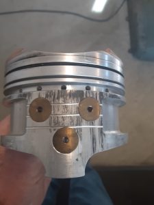
Piston alloys – There are basically two aluminum alloys used in the manufacture of forged pistons.
4032 alloy is used primarily for high performance applications under about 750 hp. This covers most of the builds you’ll encounter. This alloy has a high silicone content and is more stable (less expansion) providing a better ring seal due to tighter piston to wall clearances.
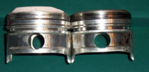
2618 alloy would be the piston of choice for high horsepower applications as they are not as brittle as a 4032 alloy. They expand considerably which explains why piston to wall clearances can be in the .010 range. For a supercharged application, .010-.012 is the minimum clearance. If the piston manufacturer says this is too much, tell him to follow instructions. With tight tolerances on a supercharged engine, skirt scuffing will occur – especially gasoline. Pistons sometimes have a .75 tang at the bottom as in my pictures above. Due to rocking in the cylinder, this is where the cracks start. Have the manufacturer eliminate this by machining the bottom to look like a “C”. There’s a little more weight involved, but it’s worth it.
Using a fine grit, I lightly sand blast the skirt on all new pistons. The tiny “pits” retain oil and helps with the skirt scuffing.
Rings
I’ve discussed my preferences (.017 chrome stainless or ductile Fire Power Dykes) under the Block section. I use a taper face ductile or standard Napier for my second and a standard tension oil set. It’s a popular practice to gap the second ring a couple thousandths larger than the top ring to avoid trapping gasses and causing ring flutter. Check with your ring supplier.
Here’s a story you might enjoy. I was on a tight schedule to get the engine ready for a race and noticed the chrome on one top .017 ring was burned off and the loss of tension due to a lean mixture in that cylinder. At the time I didn’t have any 4″ spares for replacement. A check of my “inventory” revealed a new set of .017’s for a 392 with a 4.06 bore. I decided to try this ring in my smaller bore. To my surprise the leak-down was the same as the other rings. I ran it this way until the next ring change with no difference in performance. There are a lot of 4.030 and 4.040 392’s around. Although a little unorthodox, if you can’t get a Dykes for these bores I wouldn’t hesitate to try a slightly oversize ring.
End gap – Manufacturer’s recommendations for the top ring is about .030 for a 4” bore Dykes and ductile top ring. If you grind too much off and end up over .030 don’t go out and buy a new set. I’ve tried as much as .045 with no change in performance – maybe a little more leak-down. A note about ring filers: – Buy one with a good wheel like diamond impregnated. I bought a K&D as a spare and the wheel wore out on (4) rings. Dykes and hardened ductile are tough whereas your second ring is softer – don’t over file the second ring thinking it takes the same number of “cranks” on the ring filer. File one end of the ring only and de-burr.
Ring replacement – The Dykes seal so well that you can reuse them as long as they haven’t collapsed or do not have burned areas (brown) on the face. I’ve used the same set in two blocks and over 60+ runs in each. I check the gap when new (not installed) and replace them when they start losing tension (gap gets smaller by about 25%) or I see the change in the leak-down. Supercharged gas is a different story. If lean on the main jet, you’ll notice an increase in leak-down. As noted previously you could be way lean and see 50% leak-down. If in competition, don’t panic, the rings will still seat under power. Richen things up and change the rings when you get home. With 50% leak-down you may see the brown areas on the ring face where the chrome has been burned away or decreased end gap due to a collapsed ring. If the face is burned on a chrome/stainless ring, discard.
Rods
Aluminum rods are the choice of champions. You won’t need a longer rod unless you get them at bargain prices or intend to build an all-out class engine.
I recommend purchasing new rods – it’s not worth taking a chance. If you must run a used set have them Zyglo’d and replace the bolts with a minimum ARP2000 or equivalent provided the threads are good. ARP L19 would be the best if running a heavy assembly (alcohol) or a lot of rpm. Remember to check and record the rod bolt lengths before installation.
If you are utilizing old style aluminum rods like M/T or Howard , you will benefit from my Chamfer and Pin Drilling Jig. It has a diameter that can be chucked up in a lathe for adding the chamfer. Check out the “Products” section. While you are there, check out my Adjustable Connecting Rod. I don’t get a lot of calls for this but I use mine more than anything else I make.
Steel Rods – Steel “H” beam rods are becoming more popular and are available for under $700. In December 2012, Hot Rod Magazine made a comparison of small block Chevy rods. Eagle Specialty Products listed three rods capable of 1200 – 1400 hp. They don’t have the rod bearing pin nor the cushioning effect as aluminum, but may be worth a try. Eagle claims the pins aren’t necessary – I disagree! If you decide on a steel rod, I would ask if they can install the pins. Would you rather have the bearing rotate in the rod or have bearing material on the crank? I had the nut that holds the pressure regulating spring in the oil pump come off half way through a run. The only thing left of the bearings was copper. The aluminum rods were fine – no discoloration or out of round and didn’t spin. I took 400 sandpaper to the nitrided crank and it was perfect. Kiss a non-nitrided or chrome crank goodbye! Eagle’s big block rods are about 800 grams which is comparable to an aluminum rod but you’ll need to hone your pistons for a .990 pin. A friend in our association (WFA) has been using steel rods in his supercharged alcohol Chevrolet for years. He does change the rod bolts every couple seasons. Another rod option – Pontiac. Same length as Chrysler and same journal size. The small end will need to be honed to .984.
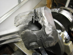
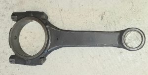
Here’s a Top Fuel rod from the 60’s. These were the hot item before Mickey Thompson started offering aluminum rods. This one is for a 354 and done by Don Alpenfels at Don’s Boxed Rods. It’s a stock rod with plates welded to each side. After welding, the rod is straightened, big and small ends are resized and the bearing pin added.
Rod Bolts – 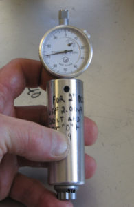 Under normal race conditions aluminum rods rarely break. It’s usually a rod bolt that fails due to excessive stretch. Check the free lengths when new and record. Electrically etch the length on the head of the bolts. Good Vibrations sells the dial indicator setup shown to check rod bolt stretch (T-1158). Their number is: 800-576-7661. You’ll need a “standard” (something of a known length) to set the dial. I use a discarded 2″ rod bolt. Make sure the end of the bolt is perfectly flat. Use a depth micrometer to check the distance from the end of the bolt to under the head. Say it is 2.005. Insert the bolt in the checker and then set the dial to read .005. Save this bolt for checking each time you use the gauge. Note: Some bolts have a hole in the end so use the indicator end that is gradually rounded (almost flat). The reading in the picture would indicate a bolt of about 1.971 in length.
There are many conditions that lead to rod bolt stretch. When I was running supercharged gas, the pistons were practically flat tops to provide 8 ½:1 compression with M/T rods. This combination was fairly light allowing 9000+ rpm without bolt failure (100+ runs). If running alcohol with a smaller displacement engine, the dome of the piston is much heavier due to the requirement for 10:1+ compression. In addition, rods purchased today are generally much heavier than my old M/T rods. This combination adds up to a much heavier assembly – one more likely to stretch the bolts. Larger displacement engines may be less prone to rod bolt stretch due to a smaller dome and a lower operating rpm. I say “may” because additional stroke also adds to piston speed and therefore stress on the bolts. The formula for piston speed is stroke x rpm divided by 6 = feet per minute. A safe number is usually 4500-5000. My gas combo is 3.625 x 9000 divided by 6 = 5438 – slightly over the safe limit. Lets look at a 392 with a ½” stroker at only 7800 rpm. 4.406 x 7800 divided by 6 = 5728 – considerably over the safe limit. As you can see the 392 would have to be run about 7400 rpm (5434 fpm) to compare with my 354 – even less to be in the safe zone. These calculations don’t consider the weight of the assembly – a lot to think about. Note: Keep in mind we’re not talking class racing where we may want to buzz this thing 10,000 rpm like a NHRA Pro Stock engine. Our limiting factor is the bore in trying to squeeze out more cubic inches. For illustration purposes let’s take the 392 above (4.060 bore x 4.406 stroke = 456 ci) and twist it 10,000 rpm. 4.406 x 10,000 divided by 6 = 7343 fpm. Wouldn’t last long! Compare that to a 500 ci Pro Stock engine with a wide bore spacing where the bore is 4.700 and the stroke is 3.600. So, 3.600 x 10,000 divided by 6 = 6000 fpm. A pretty safe combo given the availability of quality components.
Check your rod bolt lengths in a free state – then after 6-8 runs. More often if you run a lot of rpm or accidentally over-rev the engine. If you note any stretch of .002, record and reinstall. This is my recommendation since I have seen bolts stretch .001-.002 and then take a “set”. Every bolt manufacturer will give a different answer as to when replacement is required. I replace a bolt when I see the length exceed .002. If you’re one to go all season without pulling the pan, you’re looking for trouble. Better to catch a stretched bolt early.
Most rods come with at least a ARP2000 bolt. If you’re going to be running a lot of rpm and/or a heavy rotating assembly I would consider ARP L19 bolts if you are having a problem stretching bolts. They are about 50% more expensive but will last longer. I keep an extra set around and replace one at a time as needed. Manufacturers will tell you not to keep removing and re-installing the same bolts. I haven’t found this to be a problem but after the first removal where you check all (8) rods, you can go to removing two pair of rods at a time. So cylinders 1-4 this time, and 5-8 next time if concerned.
Threads – I’m not talking about the Internet. I’m talking about the threads in your rods. Just like checking the bolt lengths for stretch as discussed above, the threads in your rods will eventually wear out. Most rods utilize a 7/16-20 bolt. Purchase a GO-NOGO gage (Class 3b) to check your threads. When your rods are new, the GO portion of the gage should not start (or just barely) in the thread. When the gauge will turn approximately 1 1/4 – 1 1/2 turns, it’s time for new rods. Here’s a picture of the gage. They are reasonably priced on ebay.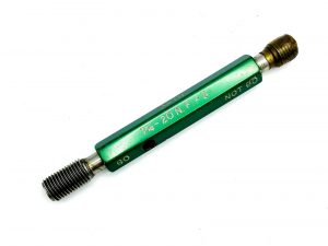
Rod bearings – If you’re running a standard 331-354 size journal you will likely need to drill the bearings for the rod pins. If the rod journal fillet radius has been increased, chamfering the bearings to permit sufficient oil flow is mandatory. As mentioned above, check out my chamfer/drill jig in the Products section. This tool makes drilling and chamfering easy and can be supplied with different journal diameters. Bearing selection: Stock size journals = Clevite 77 CB378P (P=pin for aluminum rods) or King bearings. Big Block Chevy = Clevite 77 CB743HND or if you can find them CB956P. Small Block Chevy (2.100) = Mahle CB663HND (N=narrow, D=dowel pin).
Heads
Yes the ‘55’s are the best (see the Gene Adams write-up online). My first set were ’56 Mondello heads and I burned up a lot of parts. They had huge ports with large exhaust valves. In the mid-‘70’s Steve Woods sold me the record holding heads off his BB/A. These were ’55 heads. I saw an immediate improvement in power as well as fewer burned pistons. These heads were done by Gromm in the bay area. Out of curiosity, I recently had the heads flowed and found the intakes were 313 cfm @ .600 lift and the exhaust at 235. Not bad for the ‘70’s. The valve sizes are 2.200 x 1.920. Valve length is 5.150. I still run them*. Springs for my .600 lift Engle flat tappet are Comp Cams #917 and set to 210 lbs on the seat and about 550 – 600 lbs open. Installed height is about 1.750. When selecting springs, the ideal spring installed height places the spring about .070-.100 from coil bind. For my .647 lift roller the springs are set to 280+ lbs / 650+ lbs. The junior fuel guys used Bob McKray when some of the guys ran hemis. He’s in Mission Viejo, CA. Plan on spending about $3K for some good flowing iron heads. Nick Smithberg (Smithberg Racing) has a CNC program for the iron heads and claims 400 cfm. He gets about $3K for the porting. Nick also has a CNC program for the aluminum Hot Heads. Nick did the porting for the early hemi in the Engine Masters Challenge. An impressive second place finish. Note: The spring pressures noted are for my assembly which utilizes .046 wall pushrods. Most assemblies will utilize .060+ wall pushrods necessitating an additional 20 – 30 lbs on the seat. Flow numbers – I’ve listed some pretty impressive flow numbers. If utilizing a .600 lift cam, one would have to question if a higher flowing head would be cost effective as the cam would probably be the limiting factor. Only a dyno would tell whether there’s too much head for the cam. Or, maybe someone like Smithberg already has this data.
If you want aluminum heads, Hot Heads makes an affordable set in either solid or water jacketed but you will still need someone like Smithberg to work them over as the flow is not that good “out of the box”. They flow 274/191 at .600 lift. I believe the higher flow numbers shown on the Hot Heads site reflect Smithberg’s work.
Iron heads – Plugging water holes in the combustion chamber side of the heads – I have chased water leakage problems around for years. Although mainly around the 3/8” splayed main cap holes in the block, problems can also occur with the head gaskets as noted below. If running a race engine, the best way to eliminate this problem is to plug the holes in the combustion chamber side of the head with stainless socket head pipe plugs. If at some time you want to run water in the block, the stainless plugs can be removed. The smaller holes can be tapped to 1/8-27 without drilling. The larger holes must be drilled out to 37/64 (.578) for a 3/8-18 pipe tap. You’ll also need a bottom tap for some holes. There are also small holes at the top and at the center-line of each chamber. They’re about .200+ in diameter and usually rusty. I cleaned each of these holes with a small round wire brush until all deposits were gone. I then turned aluminum plugs on the lathe about 1/2” long with .002 taper and drove them in. Unfortunately each plug must be custom made due to differences in the diameters. Use sealer on all plugs. An alternative would be to ream all holes to the same size. This would eliminate the necessity to make different size aluminum plugs. These could also be tapped for a small SS plug.
Note: Some of the 1/8-27 holes are located close to the external step in the casting. Internally the casting also steps in. When tapping these holes, the tap will start to angle when it hits this step. Proceed with caution so as not to break the tap. With sealer on the threads the plugs will still seal fine.
Here’s some general comments on assembly:
- Retainers can be a little smaller in diameter than the spring without affecting function – say 1/8″.
- Keepers – I have received some bad keepers recently so look them over closely. Buy (2) sets at a time to pick the best. About half of the keepers on two sets from Comp Cams were too small in diameter to fit around the valve stem. On another set from Manley I found the protrusion that fits into the groove on the valve stem was only .003 whereas others in my “collection” protruded about .010. I had Manley check their design and they found the protrusion was designed at .010. I received a letter indicating .003 was OK to use as the protrusion was only used for locating in the groove and the taper kept everything in place. This was not news to me but in case of valve float wouldn’t you rather have a little more tang in the groove? I threw them in the trash. When assembled, there should be a gap of say .020 between the two keepers. If the gap is close to zero, grab another keeper (or two) until you find a combination that provides a gap.
- The bevel on the outside edge of the spring goes up.
- Lube all parts including springs and shims prior to assembly. I use Comp Cams valve train assembly spray.
- I use a large heavy duty “C” clamp with a spring cup brazed on the spring end for assembly. When you tighten the clamp the valve stem will usually be slightly off center in respect to the retainer – this is good. Tighten just enough to get one keeper in the tight side. Push a little on the spring if needed. Add the second keeper and hold in place with a small screw driver. While pushing on the keeper, tighten the “C” clamp just enough to get the remaining keeper to snap into the groove. Slowly back off “C” clamp while watching keepers. This process minimizes the frustration of having keepers falling out on the floor. Whack the tip of the valve two or three times with a plastic dead-blow hammer to seat the keepers.
- Here’s something that may be of interest. Lash caps are never a perfect fit for the valve. As such, they rock a little as the rocker arm moves across the cap. This rocking will eventually eat into the valve stem necessitating new valves even when the head of the valve is good. I recently purchased some Manley intake valves with an extra .100 above the groove (.300 total) and hardened tips. This was for my late hemi. The hardened tip eliminated the need for lash caps. I’ve had no problems with these and my roller rockers. Another option is to check different manufacturers lash cap size. Some are slightly smaller inside diameter thereby providing a tight fit on the valve stem. On the exhaust side I’m using Manley’s “Bead Loc” setup where the retainer and keepers captures the lash cap. One nice thing is the large diameter of the lash cap (about 1/2″) works well with my non-roller rockers. This setup does not wear the valve stem and worth the investment. Note: Do not run lash caps with a pressed in hardened tip. Rocking of the lash caps will cause the hardened tip to come out and your valves are shot after a few minutes of running.
- The stock height rocker arm setup was designed to place the rocker arm as close to the center of the valve tip as possible as it moves across the tip. Keep in mind that cams available at the time had maybe .400 lift. Lash caps add about .100 to the height of the valve stem. Modern cams may be in the .500-.600 lift range or more. Given these variables, it is imperative the pattern across the valve tip be checked with the cam of your choice along with the appropriate valve length, spring height and pushrod length. Look for a pattern of about .030 (or less) on each side of the center-line of the valve tip as ideal to minimize side pressure on the valve and thus a reduction in friction and guide wear. This is not to say numbers greater than shown above will not work but will increase wear. To check this, take a black marker like a “Sharpie” and blacken the lash cap on one intake and exhaust valve. Add rockers and adjust lash without removing Sharpie mark. Lash can be a little loose. Rotate (2) revolutions. Remove rockers and check pattern across lash caps. An adjustable checking pushrod will aid in determining the proper length pushrod to produce the best pattern across the tip. If used, replace valve springs with light weight “checking springs”. Adjustable pushrods are shown in the For Sale section.
Head Gaskets
For anything under 750 hp (street or strip) you can run o-rings with copper/composition or steel composition gaskets (they seal water better). If you can find them, you can also run the steel/composition gaskets. I never blew one of these gaskets when running supercharged gas. When utilizing the copper or steel composition gaskets make sure the o-ring is inside the lip where the copper/steel is folded over.
If you run alcohol or nitro you’ll need the solid copper gaskets. I run .043 SCE gaskets. It doesn’t make any difference how “dead soft” the gaskets are they will not seal the oil and water effectively. The use of massive amounts of sealer is not a good idea if you want to re-use the gaskets and you don’t want to tweak them out of shape getting them off. SCE makes a gasket with a bead of rubberized sealer around the water holes, but once used, the bead is gone. You’re kinda stuck. In my case I have the water holes on the combustion chamber side of my heads plugged so my main concern is oil. These areas are: 1) Oil hole to the rocker arms at 80 psi. 2) Drain-back holes 3) Crankcase pressure causing seepage around the pushrod holes. For items 1) and 2) I use a 5/8” diameter hole saw to cut around the existing holes in the gasket – three places. Then it’s down to the hardware store for some 5/8” o.d. x .06 thick o-rings. For item 3) I use a sealer like K&W Copper Coat (dauber) around the pushrod holes in the block, head and both sides of the gasket. Note: Copper Coat goes bad after a long shelf life. Shake well and open can at auto parts store. If green don’t buy it. Have them order a fresh can.
Rocker Assembly
Nothing fancy here. I’m still using the same setup I got with my first engine. Stock intake rockers and Donovan exhausts on stock height stands. This setup twisted over 9000 rpm with the gas engine. I have a second needle bearing set. This also has the stock intake rockers with Gotha aluminum forged exhaust rockers. If you are not running a lot of spring pressure, Hot Heads or rockerarms.com (530-242-1316) can rebuild your stock assembly and install adjusting screws in the rocker arms. You could call them to see if they can add reinforcing straps along the top edge of the stock exhaust rockers. If they can, you have an assembly that will work well with spring pressures up to about 500 – 600 lbs. (open). For those that want the best, or are going to a cam over .650 lift, manufacturers like Rocker Arm Specialist and T&D also do the aluminum roller tip assemblies. You’ll have to jack the spring pressure way up for these heavyweights – probably over 300 lbs on the seat! Check with the supplier of your camshaft. Based on the cam design and the rest of your valve train, they will have a pretty good idea of the proper seat and open pressure at the max rpm you specify.
Remember, my combination relies on the following to rev over 9000 rpm with 210 lbs on the seat: Flat tappet cam, lift in the .600 range, .046 wall 3/8″ adjustable push rods, no heavy roller rockers on the exhaust. If you change any of these items, you’ll have to consider more seat pressure, particularly on the exhaust.
For reference, the stock stands measure: Intake – 1.483 to centerline of rocker shaft, Exhaust – 1.943.
Note about stock intake rockers: I noted mine are stock – completely stock. I have some of the fancy intakes that are lightened, polished and treated (reddish/brown in color). If you want to polish them to reduce the possibility of a stress crack – fine, but lightening is definitely worthless and only weakens the rocker. Even with my 2.200 intake valves, the exhaust will always float first. It’s just wasted effort.
Restricting oil flow to rockers
For a race application it is a good idea to restrict oil flow to the rockers thereby reducing oil to the top end and maximizing oil to the bearings. Depending on the rocker stands being used, do one of the following: Drill and tap the oil hole in the head under the rocker stand or combustion chamber side (both heads) with a 1/8-27 pipe tap. You can also tap the rocker stand if enough material in stand available. Use a socket head pipe plug. Drill a 1/16” hole in each plug and insert in heads. If using needle bearing rockers, slide the rockers to the side and apply assembly lube before installing. Repeat at each engine disassembly – just an added precaution. Racing only – I have a second set of needle bearing rockers with no oil hole in the stands. These have been run on and off for 20 years and are fine. I put assembly lube on the shafts a couple times per season. More lube is not necessary as there is plenty of oil flying around inside the valve cover.
Pushrods
I use 3/8″ Smith Brothers adjustable pushrods. With a stock rocker setup and solid lifters which are 1 1/8″ from pushrod cup to the base of the lifter, the pushrod lengths are 9 3/4″ for the intakes and 11 3/8″ for the exhaust. My tubing wall thickness is .046. With higher lifts and aftermarket roller rockers go with something in the .090 range. Pushrods are expensive so make sure you mock-up your assembly with a pushrod specially made for checking. If you need one check the For Sale or Products section for details. Here’s the procedure for checking the proper pushrod length:
Pushrod Length Calculation
Tools Needed:
- Adjustable Checking Pushrod
- Checking Springs – Jegs, Summit
- Black felt tip marker
Assumption: The lift of your cam is within the geometric capability of your stock rocker stand setup. This is about .640. More than .640 will require custom stands.
Once the installed height of your springs is established, assemble an intake and exhaust with a light pressure checking spring.
Using a black felt tip marker, cover the tip of the two valve stems.
With camshaft on the base circle, heads and rocker arm assembly installed and torqued, add intake lifter and checking pushrod. Adjust checking pushrod to obtain proper valve lash per cam specs. Take care as to not remove black marker when adjusting valve lash. Just start the feeler so as not to rub off the marker.
Rotate engine two revolutions.
Remove rocker assembly and view mark across valve tip.
Ideally the pattern should be centered to reduce valve guide wear. However, generally speaking, anything where the pattern remains within a circle of about 2/3 the diameter of the valve stem will work fine. So, for an 11/32 (.343) diameter stem, that would be about .226, or .113 on either side of center.
If the pattern is OK, note the intake pushrod length.
Repeat for the exhaust.
Since the hemi rocker assembly has a fixed position, there’s very little that can be done to improve the pattern across the valve. In extreme situations, the main reason for a bad pattern would be the valve length – usually too long. In this case, you could either install the proper length valve or play with stand height. Start by adding aluminum shims under the stands and rechecking the pattern. This will give you some idea as to the effect on the pattern. Roller cams over .640 lift will require custom stands that are taller with the rocker shaft moved outboard to provide the correct geometry.
Cam
I still run my original hard face flat tappet cam. It’s an Engle F31 with .600 lift, 322 degrees duration (.020 checking height) and 108 lobe centers. For what we’re doing, anything in the 108-112 lobe center range will suffice. The comparable Engle grind in a roller was the L131 – a great supercharged gas or alcohol cam if you have a good rocker arm setup. I run the hard face to keep the valve train weight down in order to rev 9000 with my stock intake rockers and aftermarket exhaust rockers. Here’s the valve timing for the F31 at .050 checking height: IO=36 deg BTDC, IC=66 deg ABDC, EO=72 deg BBDC, EC=30 deg ATDC (282 deg duration). Seat pressure is 200 lbs. and about 575 lbs. open. Remember, 331/354 and 392 take different cam blanks due to the different deck heights. Note: If you decide to run a cam with lift above .650, you will need special stands with the rocker shafts moved higher and outboard to retain the proper geometry. Custom aluminum rocker stands/rockers will also be required to handle the additional spring pressure. If this is your plan, cam selection is endless.
BTW – If you’re going with a used flat tappet cam, make sure the lifters still have the convex curve on the face before using. This allows the lifter to rotate. Often, if you lay a straight edge on the face, the end is either flat or concave. Rocker Arms Unlimited at rockerarms.com can re-radius the ends at about $5 each as of 2022.
Gear Drive
Here’s one area where I would spend a little more money on insurance. Get a gear drive. It’s not worth taking a chance on a timing chain in comparison to the damage that can occur if it breaks. I have a Donovan on mine but RCD also makes a nice one – and expensive. Buy an extra lower gear so you’re not pulling it on and off if you swap rotating assemblies. Note: Donovan no longer makes the aluminum fuel pump extension for their drive. Good Vibrations now has a 5″ (B-2126) or 6″ (B-2128) extension that fits most Donovan gear drives. It looks very similar to the old Donovan extension and has the same diameter where it bolts to the Donovan cover. I have a few of the Donovan hex collars for their pump extension if you want to make your own. These are the last of Donovan’s stock. See the “For Sale” section.
Oil Pump
I use a stock 331-354 oil pump with a square Milodon pickup (no longer available). The spring has been shimmed .290 ** to provide 80 psi before the bypass kicks in with Lucas 20W-50 synthetic oil. This has worked effectively for 9000+ rpm – meaning no oiling problems/spun bearings. If running less rpm, 60 – 70 psi cold would be OK. You can also use a Milodon or Hot Heads setup that utilizes a spacer and 340 pump. The spacer is a necessity on some stroker engines to provide additional clearance for the rods as they pass below the pump pick up. Shimming the bypass spring to increase oil pressure on a 340 pump is difficult since a small cup plug must be removed, shims added and a new plug re-installed before testing the pressure. Then, the procedure repeated several times until you obtain the proper pressure. The 331-354 pump simply has a square head on a threaded plug that can easily be removed. The overall installed height of the stock 354 pump with the Milodon pickup AND the 340 pump with Milodon spacer and pick up is 7″ from the pan rail. This is the same for a poly block. A 8″ deep pan gives more than enough clearance. For a stock stroke, I prefer the stock pump as the pump registers in the rear main cap for a near perfect alignment and provides sufficient oil pressure/volume.
** Shims over .290 could lead to coil bind thus maxing out the pump capacity of about 90 psi.
FYI – Here are the gear heights and diameters for both pumps:
354 – 1.625 diameter x 1″ tall.
340 standard (M-72) – 1.780 x .826 tall.
340 high vol. (M72HV) – 1.780 x .945 tall.
340 information above from Melling tech. Gear end play should be .002-.003.
I fabricate an oil pump pressure checker to make setting the pressure easy – Get it correct before you complete the engine assembly and save yourself a lot of time. Check out the Products section where there’s more info on the subject.
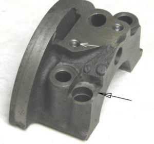 Note: There are two different oil pump mounting bolt spacing on the rear main cap (1.650 or 1.750). If your pump does not match, you can still use it by elongating the hole in the pump base flange closest to the pump drive shaft (white arrow) by .100. Elongate it parallel to the back of the engine. I’ve seen some caps with the tapped hole welded up and re-tapped. There’s no need for this. Just elongate the hole in the pump base. Some main caps must also be milled to clear a hemi oil pump shaft housing so it can locate in the cap – black arrow shows milled area.
Oil Pump Drive Gear / Intermediate Shaft
Make sure you check for engagement of the intermediate and oil pump shaft. This is easier to do with the cam out. The drive gear wants to be seated when engaged in the pump tang. With the pump out, use calipers to check the depth from the top of the block down to the top of the drive gear – record for future use (around 3.770 on a 331-354). Then check after the pump is installed. If the pump is pushing the driver up, you can add a shim between the pump and rear main cap. If the drive gear shaft is only engaging by say 1/8”, compare the shaft length and pump shaft length to other stock parts to find the problem. You may have a short shaft. Note: There are (2) different length intermediate shafts that I am aware of – 5.125 and 5.200. This measurement is from the bottom of the gear to the tip of the shaft. Both my standard 354 block and ’57 354 Poly block use the 5.200 intermediate shaft for proper oil pump engagement. The recorded depth noted above (3.770) is also helpful when installing drive gear/shaft with the cam and pump in place to ensure the drive gear is seated. Tap a 10-24 or 10-32 thread in the top of the drive gear so you can get it out if it doesn’t drop into the oil pump tang during installation. Use threaded stock or long screw as a removal tool. For reference, the distributor shaft length on a 332/354 should be (3.770+.300 down to drive slot in gear+.230/.250 engagement=4.300. This measurement is important to insure the intermediate shaft/gear can’t rise enough to put unnecessary stress on the intermediate shaft tangs as seen in the picture. With the oil pump out, the intermediate shaft can be moved to check for engagement with distributor shaft.
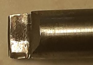 Here’s a picture of the end of my intermediate shaft. The tangs for the oil pump are about .300 deep. As seen by the wear marks, the oil pump tang is riding about .250 into the intermediate shaft. This is where you want it for 80 lbs of oil pressure. It’s hard to see but, YES, one tang is broken. But, this was with 8-years of racing on straight 50w oil and another 3-years of 20w-50. This is a stock shaft. Aftermarket shafts may or may not be stronger. You can minimize any movement – up or down – of the intermediate shaft with an aluminum split collar on the distributor shaft. You don’t want it too tight but a shaft movement of about .010 vertically would be good.
Oil filter
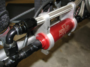 I use a System1 filter with AN fittings on each end. This does a good job without any drop in oil pressure. It has a screen inside that can be easily cleaned. Assuming no nasty bearing failures, what kind of debris are you most likely to find inside the filter? How about lint from the shop rags used to clean and assemble the engine. To minimize the lint, use closed loop towels or the common blue paper shop towels. I’ve included a picture so you can check out the trick brackets that holds the filter. If you need custom brackets made, let me know.
Oil
Lucas High Performance 20-50 Synthetic works best with my clearances (.003-.004). In the 70’s Pennzoil was my sponsor. The bearings always showed some wear and tear. With the Lucas they look new! Lucas also makes a high zinc Racing Only oil but I don’t find it a necessity. Maybe a consideration if running a lot of rpm with a flat tappet cam.
Note: Oil pressure (80 psi) as indicated above is the recommendation with the clearances noted. If you prefer an increase or decrease in bearing clearance then reconsider the oil selection.
Accumulator
What it is? An accumulator is basically a cylinder with a floating divider inside. On one side you put say 10-20 lbs. of air. When you prime the oil pump, pressure builds to 80 psi. and the divider moves toward the center to fill the accumulator with oil. At 80 psi, manually close the valve. Before you start the engine, open the valve to prime the engine. Starting the engine refills the accumulator. Leave it open. When you reach the quarter mile mark, pop the chute and hit the brakes, oil pressure can drop to zero. As pressure drops, the accumulator dumps oil into the system until the pressure in the accumulator is depleted. By that time, the rpm has dropped and you have shut off the engine without damage. Try to plumb a 2 or 3-quart accumulator into the system. Most are made by Canton or Moroso. Remember to overfill the pan with the additional 2 or 3-quarts of oil. If you don’t have room for a 2 or 3-quart accumulator, use a 1-quart. I used the smaller accumulator in my BB/GS coupe for years without bearing failure. See “For Sale” section.
Ignition
Mag or MSD? Take your choice! I’ve run both and performance is the same. I ran the Vertex until I got the tip of the fuel squirt bottle caught under the injector butterfly – 10,200 rpm per the computer! It got me thinking about a MSD.
A Vertex magneto carries the nostalgic “look” and I wish I was still running mine as this is the only item on the engine that doesn’t look ‘60’s. Tom Cirello (541-948-0547) is the best at setting these up. Many of the used units floating around have weak coils. Never run a used magneto (or a once good one that has been sitting for years) unless it has been tested. There are a couple of negatives with the Vertex: 1) no “soft” rev limiter like a MSD 2) electrical interference with on-board computers.
If going with the MSD, they make a distributor for the early hemi. I would buy the Cap-Adapt large cap for this distributor. Unless the blower (6.71) is set back on your manifold the large cap should clear. You will also need to remove the guts for use with a trigger setup – instructions included. I used the Digital 7 box, HVC-2 coil and Taylor ThunderVolt spark plug wires with the hemi ends.
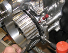 For the trigger setup I used the following RCD products: long crank hub and bolt, 7” flat alcohol degree wheel with magnets, and left side crank trigger bracket with TDC pointer . You will need to make custom spacers for the trigger bracket as seen in picture.
To ensure an adequate electrical supply you can run a small ultra mini 50A alternator. The alternator crank pulley is mounted on the back side of the degree wheel (just behind the red pointer in the picture). The trigger pickup is an Electromotion (Dave Leahy) unit. If you’re turning the engine over with a conventional type starter, gap the trigger pickup at .035. The faster the starter turns over, the wider the gap can be.
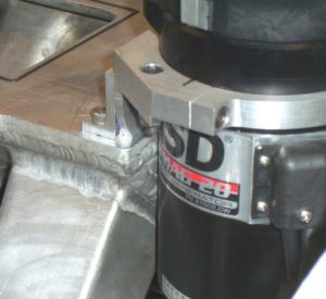 MSD ProMag – For some reason I decided the Digital 7 wasn’t burning the fuel so decided to invest $3500 in a 20 amp MSD ProMag setup (you don’t need a 44 amp). I bought mine from BR Motorsports (559-739-1515) because they had them in “Black” (I hate those red caps on a nostalgia engine). Mike Dunn Services (417-967-0528) makes the black anodized cross drive adapter for the band clamp. With the adapter, the setup is pretty tall. I fabricated the aluminum clamp shown in the picture and attached it to the top of my intake manifold for added support. For my low Cragar manifold I attached the clamp to the supercharger rear bearing cover bolt holes via an “L” shaped bracket. To date the ProMag hasn’t improved performance over the Digital 7. As a side note, one of the guys in our altered group utilizes a standard MSD distributor with a HVC coil and runs well over 200 and in the 6’s so maybe all the concern for a trick ignition is wasted time.
Spark Plugs
Champion N57DR Gap at .018 – .020 for a Vertex or MSD ProMag and .035 for other MSD boxes. I’ve recently started gaping the plugs at .018 with the ProMag and they work fine but no noticeable increase in performance.
Spark Plug Wires
Taylor makes a nice pre-assembled set with black insulator tubes. They’re under “ThunderVolt 8.2mm Universal. The part number is 85089 (black).
Blower Manifold
I use the low-rise ‘60’s Cragar manifold with the iron heads. Other than port matching it’s original. If you buy an old style manifold you will need to add a burst panel kit to be legal. Good Vibrations sells them. You can eliminate the gasket between the manifold and blower by having the burst panel plate machined for an o-ring. A blower shop or Good Vibrations can supply the correct o-ring material. In addition, assemble the engine with manifold torqued. Use a real machinist’s straight edge to check for flatness. If it appears to have high spots, lap the surface with an old cylinder head or other flat object. Coarse valve lapping compound works well. In cases of extreme warpage, assemble heads and blower manifold (without crankshaft) and place on mill or grinder. Kiss off manifold face. To test, mount blower without gasket and torque bolts. It should rotate freely. If you hear any binding of the rotors do not run. It could also be due to warpage of the blower face. If so, machine mounting face and try again. BTW – If you are going to use a gasket between blower and manifold, use the thinnest gasket possible to avoid rotor bind.
As noted in the “Head” section, I destroyed my iron head so am now running a fabricated high rise manifold as shown in the picture above. See Ignition. No increase in performance over the old Cragar.
Tap 1/8-27 in rear of manifold for a boost gauge – electronic preferred. Plumb in a pressure relief button like you see on superchargers. If you prefer you can run an electronic Autometer gauge or an inexpensive Auber digital gauge (ebay). They are less susceptible to pressure variances or breakage from vibration. Neither my data recorder or gauge agree on boost. I usually take an average.
Blower
Again, nothing trick here. Mine is a stock 6.71 – no Teflon strips for gas as they generate heat. OK for alcohol. The bottom clearance is .003-.004. The less clearance the better without the rotors rubbing on the case. A blower shop can clearance it for you. Don Hampton did the work in the ‘70’s. I also have a Dyer 8.71 stripped blower but haven’t seen any improvement in performance with my size engine. There’s a trade-off when going to a larger blower. On a small engine they take more horsepower to drive which may negate any horsepower gained by improved efficiency and the small amount of heat eliminated. Another consideration is engine size. You wouldn’t want to run a standard 6.71 on a 500″ engine. If you’re running gas in NHRA competition, a 10.71 or 14.71 on my 365″ engine would definitely be better to reduce intake charge heat and improve efficiency due to the slower rotation.
Hi-helix rotors. This is an effective update if running a lot of rpm as conventional rotors stop producing additional boost as the supercharger approaches 8000 rpm. The hi-helix rotors keep upping the boost to about 11,000 supercharger rpm. For my application, 9000 rpm x 30% over = 11,700 supercharger rpm.
The high helix rotors produce less heat so would be a prudent addition for a street setup on gas.
Blower Oil – The recommended gear oil is Pennzoil full synthetic. If it is difficult to find, you can call The Blower Shop at 208-985-7650. While on the phone you can ask them for the recommended oil level for your application. For racing only, 1/2″ above the bottom of the front gear is sufficient.
Blower Belt
Here’s a site with economically priced blower belts: polybelt.com. I’ve been buying 1/2″ pitch belts from them without any problems. As an example, for a 3″ wide x 57 1/2″ belt you would search for 575H300. Good Vibrations Motorsports gets $129. Polybelt gets $53.59 as of 3/2024. The same length in a 2″ (H200) is $36.44. Good Vibrations charges $89.
Fuel System
I use my Hilborn horizontal 4-hole from the ‘60’s with a 150-1 pump. The pump puts out 100 lbs. @ 4000 rpm. For best atomization of fuel shoot for 100 up to 120 psi – yes you’ll need a gauge or another sensor on your data recorder. Pressure is adjusted by nozzle size. If pressure is typically below 100 psi you can decrease the nozzle size on one or more nozzles. If over 120 psi increase nozzle sizes or maybe add an extra nozzle at the rear of the hat. Warning: For Hilborn or Enderle pumps, excessive fuel pressure is hard on the pump as it does not have a front rotor support.
Here’s the Hilborn nozzle sizes:
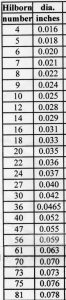
Nozzles: (4) – 27A or 30A nozzles for gas engines under 400”
(8) – 40A nozzles for alcohol. No port nozzles or high speed bypass – just something else to fiddle with. Wait until you’re comfortable with alcohol then give it a try.
(8) – 47A nozzles for low percentages of nitro. You will need the larger 175 pump or equivalent.
Alkydigger.com (or Don Enriquez at Holley in Boling Green, Kentucky) can give you the correct setup for your application. Note: If you purchased used parts, DON’T RUN THEM until you send the injector and pump in for a checkup and calibration. Here are some of the things you can encounter with used parts: 1) Barrel installed backwards. 2) Cover on pump installed incorrectly – the cover position is set depending upon rotation – front cover or belt drive. 3) Pump no good or low pressure. 4) Linkage not set correctly. 5) Butterflies not closing all the way.
Eliminate as many variables as you can before you try to fire-up for the first time. If purchasing a used pump, negotiate paying the shipping to and from the manufacturer for a checkup prior to final payment. The best price on a new pump is from alkydigger.com. Their number is: 615-457-3192.
Hilborn was purchased by Holley Performance. As of 2024, Don Enriquez was working for Holley in Bowling Green, Kentucky. If you need assistance with your injector, give him a call.
If you want to run my setup but prefer Enderle hardware, they can easily cross-reference. Just make sure you ask for a slightly “rich” setup as a starting point. If running gas you won’t need port nozzles as you want the gas to provide a cooling effect as it passed the blower rotors. If running alcohol, port nozzles are a good way to individually tune each cylinder via the EGT readings. The diameter is also large enough to pass small pieces of debris. A high-speed lean-out is a fine tuning device designed to bypass fuel (like the main jet) as the fuel pump supplies too much fuel to the engine at high rpm. See the Tune-up section for recommendations on jetting changes. On alcohol engines, a secondary bypass (comes off barrel) may be necessary to avoid going past center with the barrel adjustment and relieving pressure with the butterflies closed (See Tune Up section).
Engine Assembly Tips
Assuming you have prepped your engine components as noted above there shouldn’t be any major surprises. I am NOT going to go over every detail.
Once you have cleaned the block thoroughly (brushes in all the holes, etc.), dry it off and wipe down the cylinders with a light colored rag or “t” shirt soaked in ATF. Continue to clean each cylinder until there is no black residue on the rag. Some say grit from honing gets stuck in the honing marks and must be thoroughly cleaned. If the rag looks good you’re OK – it doesn’t have to be perfect.
Install the oil galley plugs.
Install the upper bearing halves, rear main seal and oil bypass assembly.
Oil the bearing halves with assembly lube. I use PJ1 which is the old VHT formula. It can be purchased at Jegs. Note: Anytime I mention “lube” I mean assembly lube unless otherwise noted.
Oil all crankshaft journals and install in block. Place a piece of Plastigage on all main journals.
Install bearing halves in main caps – do not lube.
Install main caps and torque down being careful not to rotate crank.
Remove caps and check clearance. Anything between .0025 and .005 is fine (.003-.004 preferred). Pick off Plastigage.
Install rear main seal and small rubber pan gasket seals in rear main cap. Add a tiny dot of silicone to the two rear main seal ends. Note: The installation of the rear main seal and pan are the only places in the assembly where I use silicone sealer. Where noted, “sealer” means Gaskacinch, Copper Coat, or your favorite.
Place (2) equal feeler gauges between the back side of the thrust bearing on either side and the thrust surface on the crank. The feelers should point up and be snug but not tight.
If running water in the block along with 4-bolt mains, add some sealer to the (6) splayed 3/8-16 holes in the block.
Lube all main bearings and install caps. Slide #3 down along the feelers.
When 4-bolt mains are used, tighten the ½” bolts (or nuts) to 100 ft, lbs, add sealer to the 3/8-16 splayed bolts and torque to 37 ft. lbs. If you can’t remove the feelers, on #3 cap and loosen cap and drop the feeler thickness .002. Reinstall cap.
Torque any un-torqued bolts/studs to manufacturers specifications.
Spin the crankshaft. If there are any tight spots, remove and locate problem.
Assemble pistons and rods. Assuming the intake and exhaust valve pockets in pistons are the same diameter, it shouldn’t make a difference how you assemble them. Hold each assembly up to the engine and determine which side of the rod has been clearanced to fit against the radius on the crank. Place a mark at the top of the piston with a black marker.
Place rod/piston in vise (protect with wood or ? – no shop rags) – black mark on piston away from you. Everyone has their favorite ring positions. The following works for me:
Starting with the oil ring assembly, place the expander gap at 6: o-clock. Place rail ends at 10: and 2:
Spiral the second ring onto the piston (start with the end of the ring perpendicular to the piston). Make sure the manufacturer’s identification mark is pointing up (or per their recommendations). Place the end gap at 6:
Note: You shouldn’t need a ring expander. There are some that say to only use a ring expander but I’ve found it very easy to over expand. The problem with the spiral method is carelessness – take your time. Start with the ring end perpendicular to the groove and then spiral it into the groove. If the two ends of the ring line up after installation, you’ve done it correctly. If not, you may have to tweak the ring ends slightly.
Spiral the top ring onto the piston. Place the end gap at “high noon”.
Repeat for remainder of piston/rod assemblies.
Add some assembly lube to a rag soaked with ATF and apply a light coat to the cylinder walls. Now you know where all the lint in the filter came from.
Select the piston/rod assembly for #1 cylinder. Lube rings with ATF and rotate in grooves. Wipe away excess ATF. Reposition rings as noted above. Add assembly lube to the piston skirt, aluminum pin button ends and rod cheeks.
Add the rod bearing and lubricate. Lubricate threads in rod. Note: If threads are in a blind hole lubricate lightly to avoid a hydraulic crack. A good safeguard is to drill a small “through” hole in the bottom of the thread to avoid a problem.
Lubricate the inside of the ring compressor with assembly lube. Note: Don’t buy a cheap aluminum ring compressor unless it is hard anodized and smooth. The ARP compressors look pretty good. Most cheapies have a rough anodized coating and the ring ends drag going in. My preference is to obtain a cylinder sleeve and cut it in half. Place in a lathe and turn a taper from about .150 larger than your bore down to about .005 larger than your bore. Use a fine stone cylinder hone or sandpaper hone to smooth the surface if rough.
Using “chop sticks” or other protective devices in the rod bolt holes, slide the piston/rod through the ring compressor.
Tap head of piston with a plastic dead blow hammer while you keep quite a bit of tension on the “chop sticks”. Once below deck, twist rod to align with cheek on throw and pull into place. Make sure the serrated rod end doesn’t hit the counterweight on the way in.
Add Plastigage to crank throw.
Add bearing to cap, lube bolt threads with rod manufacturers recommended lube, under head of bolt, seat in rod and both sides of washer (bevel toward bolt head). Install cap.
Torque or stretch to manufacturer’s specifications.
Remove cap and check clearance – .003-.004 preferred but not critical as it will measure different once engine is fired. If you see .001, PANIC!
Pick off Plastigage, lube bearing and re-install cap.
Tighten rod bolts but don’t do final torque.
Continue with remaining cylinders.
When all pistons and rods are installed, proceed to torque or stretch all bolts to manufacturer’s specifications. Less likely to forget one if all done together. Anytime you take a break, make a paper note as to where you are with the assembly (of particular importance if you are a member of the “senior” community). I’ve included an Excel spread sheet for recording torque values, stretch, etc. Print this off and fill in items like “Prior free length” for keeping track of bolt lengths, Condition of threads, Recommended bolt torque, Recommended stretch, and bolt type. Check the “Done” box when complete.
Slide the four pair of rods side to side. If they move freely you’re “good”.
Rotate the assembly to check for any unforeseen clearance problems. If encountered, back to square one. If OK, rotate #1 around to approximately TDC.
Install oil pump.
Install baffle and pan.
Install a large degree wheel. I recommend one like a Comp Cams 16”. Locate TDC – refer to on-line instructions from Internet – there are hundreds. Use a 1” dial indicator on a magnetic base. A cheap dial indicator is available on e-bay, Harbor Freight or ??? You will also need it for degreeing the cam.
Install cam “straight up” or a couple of degrees advanced to start.
Install front cover if not already done.
Re-install degree wheel at TDC.
Remove tip on indicator and replace with welding rod long enough to reach pushrod cup in lifter. Position in center of intake or exhaust lifter. Zero indicator.
Check valve opening and closing events per the cam card supplied with the cam. These will normally occur at .050 rise on your indicator unless otherwise noted on the cam card. If within +/- 2 degrees you’re ready to go (best to be a little advanced – cam begins to open sooner than degree on cam card). If not, adjust cam or crank gear as necessary. If you feel like fiddling with cam timing do it later. I think you’ll find it isn’t necessary at this time since there are too many other variables affecting performance.
When finished with the cam, move crank/degree wheel CLW to 27-29 degrees BTDC for gasoline or about 33-35 degrees for alcohol (#1 cylinder with both lifters down). Do not rotate the engine until after ignition is installed.
Add engine oil through valley and install valley cover.
If using head studs, lightly lubricate threads in block and run them in just a little tighter than snug. Do not over tighten or drench in oil as this could cause the block to crack.
Clean block, heads and head gaskets with lacquer thinner.
Copper Coat block, heads and both sides of head gasket around pushrod holes only. If running water in heads and block, goop all surfaces. Allow to dry at least 15-minutes before assembling.
Add head gasket to block. And, if going my route, three 5/8” o-rings.
Lower head into place. Stop just shy of seating and check the o-rings to make sure they haven’t come out of the gasket. If OK, continue down.
Repeat for opposite side.
Lube valve and rocker tips as well as pushrod sockets and install rocker assemblies.
Lubricate both sides of washers along with bolt or stud threads/nuts.
For ½” studs, torque the top row to 105 ft. lbs. and the bottom row to 90 ft. lbs. The bottom row is closer to the edge of the gasket and requires less pressure to ensure the block and head surfaces are parallel after torquing.
If using 9/16” studs, I would torque the top to 130 ft. lbs. and the bottom to 110 ft. lbs.
Install intake manifold and torque grade 8 bolts or cap screws to 37 ft. lbs.
If utilizing a MSD trigger setup on driver’s side, move trigger pickup until top of magnetic pickup diameter is just below magnet. Fine tune timing on start-up.
Pre-oil engine with a home made driver and drill motor. Check for proper oil pressure and fill accumulator if not previously done. Remove driver. Check for leaks. Note: Driver should have a scribed line on top that is in line with slot in bottom. If there is no scribed line, add one so you can tell where to position the slot in the intermediate shaft.
Drop in the intermediate shaft/gear. Reposition if needed by utilizing the scribe line on your driver. This will take some time to get the body of the distributor or mag in the correct position for your spark plug wires. Check depth down from top of block to top of gear at 3.770 on a 354. If considerably less than 3.770, the intermediate shaft is not fully down into the oil pump tangs. If you are having difficulty with this step, the oil pump can be loosened. Note: I do not have the depth for a 392.
Install supercharger.
Install crank trigger distributor. With the centerline of #1 terminal in cap transferred to the distributor body, rotate body until the rotor is centered on the mark. Your engine should still be at your desired timing mark on the degree wheel.
If using a magneto (not MSD) for racing it should be locked out (no centrifugal advance). Pre-set timing with a “buzz box” or you can make a cheapie utilizing two wires, flashlight bulb and batteries. Connect one wire to the case and one to the side “kill” terminal (kill wire removed). Snug distributor hold-down. With the rotor between cylinders, the light will be illuminated (points closed). While applying a little pressure to the rotor against engine rotation, rotate mag body until the light goes out (points open) at #1 cylinder and ?? degrees on your degree wheel. When complete, back off engine and bring back up to desired degree on degree wheel to re-check when light goes out. Warning: Don’t get your hand close to the standing coil wire while adjusting or you’ll be picking yourself up off the floor. Tighten distributor clamp. Install cap. Make final check with self powered timing light (like a Flaming River FR1001 or MSD) and engine running.
Add pushrods and set valve lash.
Add remaining accessories, etc, etc, etc.
Place assembly in oven and bake for 45 minutes at 375 degrees – just checking to see if you’re still awake!
OK, I guess we’ve got it! If I’ve missed anything, please drop me a line. Proceed to the “Tune up” section.
Tune-up
Establishing a baseline tuneup is very time consuming. Most of us spend years at the track perfecting the performance. The expense is enormous. A more cost effective method is to stick your engine on a dyno. Once the dyno produces decent numbers, record the weather data for use in a good tune-up program. Now, you’re ready to hit the track running.
The following tune-up information assumes you do not have the luxury of a engine dyno session to establish your baseline.
I’ll cover some general information first followed by some specifics for my gas and alcohol applications. An important thing here is the use of EGT’s to avoid burning things up. If you have questions by all means call me or drop me a line, especially if new to a supercharged setup. Best not to assume you can do some tweaking at the track and figure it out on your own. This is a formula for disaster – think I heard this phrase somewhere before. Most manufacturers like FIE, alkydigger.com or Enderle can get you pretty close on the setup for your specific engine as well as explain how the individual components function. A phone call could save your engine. As of 2024, Don Enriquez (Hilborn) was still at Holley in Boling Green, Kentucky. Another good source of information.
On-board computer – If you have the resources ($$$) I would invest in a computer from a reputable company. The more you spend the more features you get. On the high end units you get (8) exhaust gas temperature (EGT) sensors. The “ideal” temperature doesn’t always equate to the best performance. They are good for pinpointing your mistakes. For example, if you burn things up at a certain exhaust gas temperature at least you know enough to back things off (richer) to avoid doing it again. Make sure you get a pressure sensor for blower boost. I also “T” into the same line and use an electronic tell-tale gauge (like an Auber from ebay). The computer and gauge never agree so I usually take an average. The gauge also gives you a quick visual.
EGT’s and alcohol – I use a max temperature for tuning. You may ask: “What is the preferred max temperature?” I don’t know! Having said that, I will explain. I have tried three (3) different EGT devices. My computer may say 1300 degrees (average) while my dual pickup FAST unit says 850 degrees. A dual pickup (unknown brand) I borrowed from my cousin says 1000 degrees. Many will say 900-1200 degrees is preferable (gas would be higher) but which brand do I believe? It’s really not important. You need a performance baseline for comparison. Start on the low side (temperature) and gradually lean on it until you see a positive difference in performance. When you get to the point where a jet change makes little or no difference, you’re probably close to the “sweet spot”. Once you’ve achieved maximum performance, your baseline is established for a track at a particular altitude. Make note of the weather data and the max EGT reading. Shoot to maintain this reading mainly through pulley and jet changes in conjunction with you weather station and tune-up program. If most of your racing is done at about the same altitude +/- 1000 ft. I would just use your weather station to make a jet change and leave the pulleys alone until you gain experience. Due to changes in altitude or other atmospheric conditions, don’t expect to run the same times as your baseline but this method should keep you from burning things up. Summary – Any EGT system would be acceptable as long as you establish a baseline. If you can’t afford an on-board computer, at minimum, go to ebay and purchase (2) digital EGT displays (one for each side) from Auber. They are a little over $100 each and will assist in the tune-up. These units have an output for a warning light. I use a shift light with red lens. I set my Auber EGT warning light to come on at 1300 degrees with alcohol. If you see the red light, shut her off and richen it up for the next run. You can move the EGT pickups around until you find the hottest (leanest) cylinders. It’s also good to note the cooler cylinders as there is a performance opportunity by bringing all cylinders close to the same temperature. You might have some success by changing nozzles in the hat, but in general, adding port nozzles is the most effective method with alcohol. Normally, port nozzles are not used on gasoline due to the necessity of cooling the intake charge which is done through the nozzles in the injector. Another gasoline factor would be the small nozzle orifice diameters needed if port nozzles are used as they would be prone to clogging.
Weather Station – Purchase a hand held weather station. I use a CompuTech but most any will do. Once you enter your nozzle sizes and baseline main jet (pill) diameter, the unit will display all kinds of good data. You will mainly be dealing with the air density ratio (ADR) if you don’t have a tune-up program. The ADR can change drastically throughout the year at the same track. Using your baseline data, the weather station will calculate changes in your main jet based upon current weather information. If you change tracks with a big difference in altitude you will need to change your drive pulleys accordingly to maintain a similar air/fuel ratio (AFR). This weather station is not sophisticated enough to make both calculations. When racing at a new track with differences in altitude and ADR, you may need to establish a new baseline for your weather station. This is where a good tune-up program comes in handy. For me, it works out to about one tooth per 1000′ change in altitude.
Tune-up program – As noted above, the weather station is not capable of accommodating pulley changes due to an altitude changes. Since 2017, I have been using a tune-up program available from Jim Maroney at American Flowtech (amflotech.com). To date it has always been accurate and never burned anything up. Once your baseline is established, you can enter the weather data and any pulley change to obtain the correct air/fuel ratio and main jet required. If you are going to be making pulley changes, this is a “must have” program.
Leak-down Tester – Purchase a leak-down tester. In addition to leakage past the rings, the tester helps locate leakage at the valves – stick your ear close to the exhaust and intake to detect the leak. Be sure to do a leak-down before disassembling the engine. When comfortable with your AFR and performance, do a leak-down every couple runs (every run if making jetting changes without the use of a tune-up program). If running supercharged gas, do a leak-down after each run. If lean on the main jet, the additional heat can take a significant amount of tension out of the rings in addition to scuffing piston skirts, etc. You want to catch it early. A rich condition just slows things down. If running alcohol, a lean condition is definitely “not desirable”. A rich alcohol mixture is more forgiving – no big change in performance if jetting is in the ballpark and zero ring problems. Note: I recommend a leak-down tester that is capable of 100 lbs of air supply. Some of the cheap ones and even Snap-On are low pressure. You want higher pressure to “snap” the rings against the cylinder walls as this is what happens in a running engine. Mine is an old ’70’s Child & Albert with a single gauge. I set the regulator on the compressor to 100 lbs, adjust the needle to zero and have at it.
Note: Still detect a leak at the intake or exhaust? When you are doing a leak-down and cranking the engine over by hand, the valves seat lightly. If you detect a leak, whack the top of the valve with a rubber hammer and see if it stops. If so, you’re good to go. If you still detect a leak you will need to remove the head and check the valve for proper seating. Depending on valve size (weight), the valves sometime “droop” due to heat after a run. It is advisable to turn the engine over a revolution once you get back to the pits to minimize droop. If you find a valve slightly bent, you can straighten it with a valve “tweaker” . I purchased this one but they are no longer made. If you want to make your own, the picture gives you a good idea of construction. There is a bolt beneath the valve stem to adjust height. I’ve been using mine for about 7-years. I don’t know what the limit is for a SS or titanium valve but a few thousandths is OK.
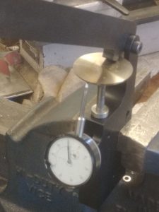
Important – NEVER run a supercharged gas engine with iron heads unless water is circulating in at least the heads. Without water, the intake charge will get super hot and you will sneeze the blower! Aluminum heads will dissipate enough heat to work OK. I recently tried running my cast iron heads without water when utilizing alcohol – worked fine as the alcohol provided enough cooling to preclude a “sneeze”. They were cracked and leaking so gave it a shot without water. I was also able to remove about 60 lbs (radiator, pump, etc ) from the car. The downside would be making the final rounds of eliminations. The heads are still pretty hot after a half hour or so. You could devise a remote setup to pump water through the heads between rounds or a fan – 10 minutes would do the trick.
Valve settings – With a new setup I would check the valves after each of the first three runs to see if there is any movement (like something wearing or a bent pushrod/valve). If OK, button it up and forget about it unless there is a noticeable change in performance. Some fiddle with valve settings after every run – not necessary with cast iron heads and block unless you over rev it. If running a roller cam and/or aluminum block or heads, more frequent valve adjustments will be necessary. Note: Don’t let this information discourage you from checking the valves after every run, time permitting! I’ve been running my combination with a flat tappet cam for over 50 years and have yet to have a change in valve lash adjustment with iron components. Having said that, I once had the push rod come off. Leak down was great but only running on (7) cylinders.
Hilborn Metering Valve – Rotor Placement – A problem that often arises with a Hilborn setup is rotor placement. This usually occurs when a used injector is purchased or the rotor is installed upside down. I always recommend sending a newly purchased injector and pump in for a check. Every aspect of the injector gets checked as well as the pump flow and new seals. For your setup, nozzle sizes, pump size, and metering valve rotor number may need changing. You will also get a recommendation on the main jet size to get you started. It’s worth the investment.
For this discussion, it’s rotor placement. If the rotor is upside down, the engine will usually quit when the throttle is opened.
When you look at the metering valve “block”, you will notice the main inlet and the outlets to the injector nozzles are offset in relation to the body – they are not on center. Here’s a primitive picture:
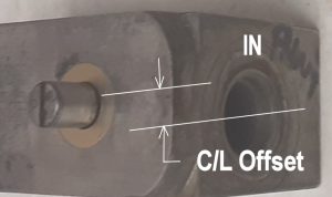
If you view the small end of the rotor, installed in the metering block assembly, you will notice a number and a slot – main inlet on the metering valve assembly to the right.
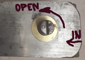
At idle, the number should face the main inlet with the slot pointing straight up. Actually, the slot should be biased just slightly in the direction of the injector opening. In this example, as the throttle is opened counterclockwise, the numbers move to the top of the block and the slot is in aligned with the main inlet. At this point, the cutout in the rotor is facing down and toward the short side where the lines exit toward the injector or port nozzles. When the rotor is installed upside down, the cutout rotates to the long side and fuel is cut off. Note: There are different numbered rotors so make sure yours is correct for your application.
If the rotor in your metering block assembly is aligned as described above, your engine should start. Idle mixture adjustment (hex rod) will still be necessary to fine tune as described next.
Hilborn rotor setting on gasoline and alcohol – If set at the factory, the rotor position is usually set at a percentage of leak-down. I don’t find it necessary to be obsessed with this number as each engine/size will require a different leak-down. You’ve probably heard people talk about “milking” the oil. This refers to a very rich idle mixture where fuel saturates the oil and turns it milky – sometimes seen on alcohol or nitro fueled engines. Excessive fuel in the oil inhibits the lubrication properties so you want to avoid this. If you follow the procedure below, your idle mixture with gas or alcohol will be on the lean side and not milk the oil. By using this procedure, I have never milked the oil.
Do not use the “hesitation” procedure described below with nitro
Setting your metering (barrel) valve
Prior to your first “fire up”, note the position of the hex turnbuckle with left and right rod ends connecting the butterflies and metering valve. Mark one of the flats for reference. Shortening (moving the rotor in the direction of full throttle) richens the mixture at idle. Lengthening the distance leans the mixture.
After the engine is warm, quickly flick the throttle by hand at the injector (about ¼ open and immediately closed) . If the engine hesitates (lean mixture), shorten the distance between the two rod ends until the engine just quits hesitating, then turn the hex an additional flat or two. If on first time startup the engine does not hesitate, lengthen the distance until it does and then richen an additional flat. If your car is equipped with an automatic transmission, put the transmission in gear and do a stall test (on jack stands). If the engine starves for fuel (too lean) when you open the butterflies momentarily, richen until it quits and then give it an additional flat. Note: The rotor setting has no effect on full throttle fuel flow unless you adjust way past where the screwdriver slot is straight across. Once the idle mixture is set, further adjustment is usually not necessary even with jet changes. A note on supercharged gas engines: A rich gasoline mixture is indicated by black smoke. If on initial startup the engine is puffing black smoke, lean the barrel until the smoke diminishes then proceed as noted above to fine tune the idle mixture. After the final adjustment to the barrel, note the position of the screwdriver slot at full throttle. It should be close to straight across and in-line with the fuel inlet. I doesn’t have to be perfect. If it goes considerably past straight across you may need a secondary bypass to bring it back – this is not normally required when running gas. I’m now running alcohol so my secondary is set to 6 lbs from the factory. Add a couple of the thin shims (more fuel on idle) and re-adjust the barrel to lean the idle mixture. Readjust until slot position is straight across. With alcohol you will always experience some condensation under the valve covers and in the pan. This is why it’s a good idea to remove both valve covers and pan when you return from the races. If you’re into a percentage of leak-down at idle, record the percentage for future reference.
Once the metering valve is set, you may want to record the leak-down. The RBS Superchargers website has this procedure listed under “Support” / “Tech Support”
Jetting – general comment. When making jetting changes consider the “area” of the size “pill” you will be using. Let’s say you make a run using a .125 main jet. You check your plugs and find you need to go a little leaner (larger) on the main jet. .002-.005 larger would be the max recommendation rather than .010 because the increase in “area” is substantial when up at .125. In contrast, let’s say you’re going to try for a little more mph by incorporating the “high speed”. Unless already running lean, you can safely go from a .020 to a .040 because there is very little change in “area” at these smaller diameters.
Spark plug reading – I don’t read rings of heat. If you are used to that method, use it. I realize everyone has their favorite method but my plug porcelain is short and very difficult to read. Over many runs, I found that an Auber EGT reading of about 1250-1275 degrees provides the best performance. I set my Auber EGT warning light to come on at 1300 degrees. This is on my leanest cylinder. You’ll have to move the EGT probe(s) around to find the lean cylinder. Since I have a pretty accurate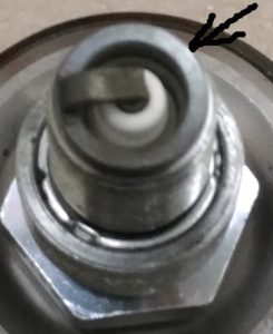 tune-up program, the temperatures are always between 1240-1275. At this temperature I burn about 3/4 of the cad plating off the face of the plug. This is my sweet spot to keep from burning up pistons or rings. On the next run, as a safety precaution, I install a new plug in my lean cylinder so I have fresh cad and porcelain to check. In the last 50 runs the plugs always look the same. In essence, I can run all year long and never change a plug. The downside is that a little more cad gets burned off with each run so eventually you can’t “see” a lean condition should it surface. Here’s a shot of a NGK B9es from my hottest (leanest) cylinder after 1 run. The arrow is pointing at the remaining cad plating. Warning: Spark plugs of other brands or heat range may show a different pattern. The NGK B9ES shown here is out of my late model hemi and not the 354.
Note: Do not idle the engine prior to reading plugs – shut off clean to eliminate a false reading.
If you have time between rounds, you can also cut the plug in half to get a good read on the porcelain. The hole saw shown if 5/8″ diameter from the hardware store.
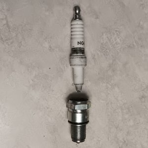
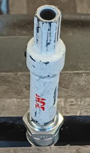
Here’s a good article on reading plugs from Steve Morris Engines at Engine Builder Magazine 9/2023: https//www.enginebuildermag.com/2023/09/how-to-properly-read-your-spark-plug/
For some reason I couldn’t get this link to work in this write-up. Copy and Paste into your browser.
Timing – A supercharged early hemi on gas likes 27-29 degrees total. You can safely reduce the timing but I haven’t found it necessary to go much higher than 27-29 degrees on gas. Alcohol is somewhere between 32-35 degrees. Any of the mentioned numbers will work fine to start. If you are checking your spark plugs for timing, a heat ring on the strap near where it attaches is about right.
Blower boost – If a supercharger is new to you, I would recommend around 18-20 psi boost as a starting point for racing and 6 – 8 psi for the street. After you get a little experience, you can “jack it up”. If you arbitrarily run the blower faster (smaller top pulley or larger bottom pulley), remember to richen accordingly. Your tune-up program will get you close.
Blower drive ratio recommendations in the examples below are for 365 cubic inches with a good 6.71. If running a 8.71, slow it down about 10% from examples below. Disclaimer – Each engine combination is different and could lead to substantially different results. Start rich! The numbers below represent actual (good) runs at various air density ratios – use them as a guideline. Something to keep in mind: If you are running a 392 you will have to spin your 6.71 about 10% faster than for my 354 to produce the same boost. For a 450 incher, tack on an additional 15% over the 392. The higher ratios are pushing the effectiveness of a standard 6.71. For example, the 450 inch engine would run better with an 8.71 at 10% less overdrive as this would bring the percentage of overdrive more in line with the effective range of the blower and produce less intake heat. Heat robs power – especially if running gasoline. Note: As a starting point, Weiand has a boost chart for various size engines. At last look it could be found at: Holley.com – Support – Tech Services – Resource Services & Library – Superchargers – Supercharger Tech Information.
Tune-up Recommendations with Hilborn 150-1 pump and 6.71 (see below) – Refer to your weather station for jet changes at different Air Density Ratios (ADR). Note ADR’s in the ’80’s are higher altitude tracks. These are my actual readings that could change slightly since this was pre-EGT or O2 sensor availability and any other modern tuning aids.
Supercharged gas: ADR = 100, Blower = 15% overdrive (boost = 19 lbs), nozzles = (4) 27a, main jet = .120, magneto = 27 degrees, fuel pump = Hilborn 150-1.
ADR = 88, Blower = 20% over (boost = 17 lbs), main jet = .150
Note: A super rich mixture on gasoline may miss or pop. If this occurs, lean the mixture (larger diameter Hilborn main jet) in .010 increments until it stops. If this happens, check your burst panel for a bulging condition. A super lean mixture will not miss – just burns things up – this is why I recommend using the EGT warning light.
Supercharged alcohol: ADR = 97, Blower = 14% (boost = 17 lbs), Nozzles = (8) 40a, main jet = .060, MSD = 27 degrees, fuel pump = Hilborn 150-1.
ADR = 80, Blower = 20% (boost = 16 lbs), main jet = .050.
For 7.60 class like NE1 at Bakersfield, CA with 2200 lb car: ADR = 94, Blower = 8% underdriven (boost = 12 lbs), main jet = .070, MSD = 22 degrees. This is my low altitude (west coast) tune-up.
Supercharged 10% nitro: 10% Nitro: ADR = 91, Blower = 17% (Probably better at 14%), Main jet = .030, Nozzles = (8) 47a. MSD = 29 degrees. Ran 4.54 @ 150.1 1/8 mile.
Supercharged 20% nitro: ADR = 85, Blower = 17%, Main jet = .030. MSD = 27 degrees. Ran 7.31 ¼ mile shutting off at 1000’ (nosed over) – Burned tip off of one plug (no piston or ring damage) – Hilborn 150-1 pump maxed out. The 150-1 would work OK on 10%. Would need to upgrade to a Hilborn 175 for the higher percentages. Nitro notes: Percentages up to 50% will work fine with 9:1 compression. However, these higher percentages will reduce the life of the engine block and crank due to increased cylinder pressure in conjunction with the thin deck. If you decide to run a higher percentage you will need to increase the timing accordingly to compensate for the slower burn rate of nitro. As an example say 55 degrees advance for 50% nitro. You can prorate the timing starting at 35 degrees for 10% to get you in the ballpark. For safety reasons start at a conservative number.
Starting the engine – Before starting, place pan under pump. Remove line from pump to injector at the pump. Check for fuel. If dry, fill fitting with fuel and turn engine over by hand (ignition off) until fuel from tank spills over fitting. Reconnect line. Turn ignition “on”. Open butterflies. Using a pump type squirt can, squirt about 7-8 times into injector. Close butterflies completely and keep them closed. Hit starter. When engine starts to run, continue squirting fuel through the small crack where the partially open butterfly meets the injector casting until the engine is running smoothly. If engine dies, repeat process. If using an upright injector with scoop, just continue squirting into the scoop. I like the pump type squirt can because it is easier to control the amount of fuel. The “beauty shop” plastic bottles tend to dump too much fuel into the injectors. I use racing gas in the squirt can or a combination of gas and alcohol for the alcohol motor. Cold weather – use gasoline.
Alcohol – Add Klotz “Uplon Fuel Lube” to your alcohol. If used as directed there is no negative effect on performance. Klotz adds valuable lubrication to your pump, shutoff and barrel which alcohol lacks.
Engine won’t start – There are many reasons for an engine not to start. BUT, If you are using a MSD unit with a standard starter, try moving the trigger pickup a little closer to the trigger wheel. I use the Chrysler gear reduction starter and run a .035 gap. The faster the starter turns over, the wider you can make the gap. A 16 volt battery is the way to go and you can use it safely with your 12 volt electronics.
Car runs way too fast and quick – A shit eating grin is a sure sign of a happy racer! I’ve been there!
After the race – You will need to flush the fuel system as alcohol is very corrosive. If alcohol is allowed to dry it forms a residue that resembles soft wax. Obviously, you don’t want this. I use a male AN fitting with an air fitting. Blow air through all lines and injector barrel valve to purge all alcohol. Then squirt some Marvel Mystery Oil in inlet line to injector metering valve. Again, blow air through the system to lubricate. You can also open and shut butterflies to lube the various bypass valves. After disconnecting the fuel source, squirt Marvel Mystery oil in the outlet from the fuel pump . Crank the engine backwards to lubricate pump. You should now be ready for the next time out. Note: If wax from dried alcohol is found, gasoline will dissolve it. Don’t forget to wipe the fuel tank dry. If completely dry, no need to use the Marvel Mystery Oil. BTW- You can also start the engine on gasoline using a large main jet prior to flushing with Marvel Mystery oil.
As mentioned previously, if you notice any errors, omissions, items out of sequence, or just disagree, please let me know. Your comments are appreciated.
Check the “Revisions” section below occasionally as I am continually making updates, additions and/or corrections.
If you feel this information has helped you get your setup up and running, or if you encounter a problem along the way, let me know. I’m always updating to provide help.
Thanks, Ed Middlebrook
Revisions – reference these dates if you have not been on the site for some time and previously printed any portion of the text.
1) 1/25/11 – Original
2) 2/8/11 – Under “Installation of new and used 4-bolt main caps”, changed to: Mill #1 and 5 caps (if originally on block) down .010-.020. See 14) below.
3) 2/8/11 – Under “Installation of used 4-bolt main caps”: added drilling and tapping instructions as in “new” installation – text missing.
4) 2/19/11 – Added warning under “Block cleaning” about possible interference between the large rear pipe plug and the distributor drive gear.
5) 2/19/11 – Under “Pistons” added a minimum piston to valve clearance note at item 2.
6) 2/20/11 – Block – Oil bypass assembly: Revised text for diameter of restriction (was .440) and removal of stock assemmbly.
7) 3/10/11 – Added “Spark Plug Wires” section and bottom clearance on blower.
8) 3/22/11 – Added text to “Blower Manifold” section for flatening mating surface. In “Engine Assembly Tips” added ATF lubrication requirements to rings prior to installation.
9) 3/31/12 – Block / Block Filling – Modified block filling procedure.
10) 3/31/12 – Crank – added “Update” re: crank life.
11) 3/31/12 – Oil Pump – Added text re: poly block rear main cap modifications.
12) 3/31/12 – Tune-up / Hilborn barrel valve setting – Added text re: shimming the secondary if the barrel screwdriver slot goes past straight across.
13) 3/31/12 – Tune-up / Starting the Engine – Added note about priming injector pump.
14) 1/26/13 – Under “Installation of new and used 4-bolt main caps”, changed to: Mill #1 and 5 caps (if originally on block) down .005-.010. This came from my machinist as he would rather take more time dealing with the reduced tolerance thereby ensuring a better rear main crank and gasket seal.
15) 1/26/13 – Added section for “Rod Bolts”.
16) 1/26/13 – Added Nitro tuneup info.
17) 03/01/13 – Added EGT section under “Tune-up”.
18) 03/06/13 – Added MSD ProMag to “Ignition” section.
19) 03/12/13 – Added Intermediate Shaft Bushing under “Block”, Steel Rods under “Rods” and bearing selection under “Main bearings” and “Rod bearings”.
20) 04/09/13 – Added note on main bearing runout in the “Used cranks” section.
21) 11/24/13 – Corrected BBC rod bearing number under “Rod Bearings”.
22) 04/01/14 – Added F31 cam specs to “Cam” section.
23) 04/01/14 – Added “After the Race” in Tune-up section.
24) 04/01/14 – Changed ignition timing recommendations in Tune-up section.
25) 12/16/14 – O-ring / receiver grooves – added text for using (2) o-rings.
26) 12/18/14 – Added picture and text re: poly block under “Block”.
27) 12/18/14 – Added picture and text re: o-ring tool under “O-ring”.
28) 12/18/14 – Added picture and text re: rear mail poly cap mods for oil pump under “Oil Pump”.
29) 12/18/14 – Added additional text for modifications to used 4-bolt caps under “Block” and picture of 1/4″ endmill cut.
30) 12/18/14 – Added additional tune-up information under “Tune-up”.
31) 12/21/14 – Added picture of ProMag stabilizing clamp under “Ignition”.
32) 12/31/14 – Added additional information under Tune-up/Nitro notes.
33) 12/31/14 – Modified wording for checking stroker clearances under “Stroking”.
34) 07/13/15 – Corrected BBC rod bearing callout under “Rod Bearings”. S/B CB743HND or CB956P.
35) 08/01/15 – Added comment about a billet rear main cap under “Block”.
36) 09/21/15 – Added picture and text in “Rod Bolt” section.
37) 10/08/15 – Added “Note” about exotic prep of stock intake rockers.
38) 02/11/16 – Added recommendations for a leak-down tester under “Tune-up”.
39) 02/11/16 – Added comment about port nozzles and high speed lean-out to “Fuel System”.
40) 02/11/16 – Added comment about tip on indicator under “Rod Bolts”.
41) 07/27/16 – Added rod bolt recommendations under “Rod Bolts”.
42) 07/27/16 – Added “Assembly tips” under “Heads”.
43) 03/06/18 – Updated as much as possible to accommodate for lost data.
44) 03/13/18 – Updated numerous sections after data recovery. Should be close now.
45) 06/06/18 – Added note about using Klotz in your alcohol.
46) 12/13/18 – Added “Jetting” and “Spark plug reading” in the Tune-up section
37) 02/18/19 – Added stock rocker stand dimension to “Rocker Assembly”.
38) 02/18/19 – Added “Pushrod” section.
39) 07/09/19 – Changed Piston dome thickness from .250 to .200 for gas and from .200 to .150 for alcohol. These were previously thicker for safety reasons.
40) 1/20/22 Added the use of a GO/NOGO gage for checking connecting rod threads.
41) 9/5/2022 Miscellaneous cleanup.
42) 10/14/22 Added rotary valve on Hilborn metering block setup.
43) 3/16/23 Added text to Compression section and skirt button picture to Piston section.
44) 5/22/23 Added Hilborn nozzle size chart and Klotz picture. Under “Blower boost” – Upped starting boost at 18-20 lbs since the sweet spot will likely be closer to 25 lbs.
45) 9/20/23 Added oil pump information under “Oil Pump”.
46) 9/30/23 Added the link for reading spark plugs. Also, made a complete update of spelling errors, etc. This would be the same as my end of year update.
47) 10/23/23 Revised valve to piston clearance information. Revised valve pocket in piston information.
48) 1/2/24 Final year end clean-up. Spelling, minor revisions, etc.
49) 2/26/24 Added Polybelt.com under Blower Belts
50) 1/15/25 Deleted section on installing used 4-bolt caps. Year end updates.
51) 6/29/25 Revised the “Welcome” page and added comment about mismatched main caps to “Block” section.
52) 6/28/26 Added roller thrust bearing process to “Main bearing” section.